1-13
!6 ACCESSORY SOCKET 1 A [ACC 1–A]
!7 ACCESSORY SOCKET 2 A [ACC 2–A]
!8 ACCESSORY SOCKET 1 B [ACC 1–B]
!9 ACCESSORY SOCKET 2 B [ACC 2–B]
Enable connection of external equipment such as
a linear amplifier, an automatic antenna selector/
tuner, a TNC for data communications, etc.
•Seepage1-14forsocketinformation.
@0 ALC LEVEL ADJUSTMENT POT [ALC ADJ]
Adjusts the ALC levels.
No adjustment is required when the ALC output
level of the connected non-Icom linear amplifier is 0
to–4VDC.
@1 ALC INPUT JACK [ALC] (p. 2-7)
Connects to the ALC output jack of a non-Icom lin-
ear amplifier.
@2 T/R CONTROL JACK [RELAY] (p. 2-7)
Goes to ground when transmitting to control an ex-
ternal unit, such as a non-Icom linear amplifier.
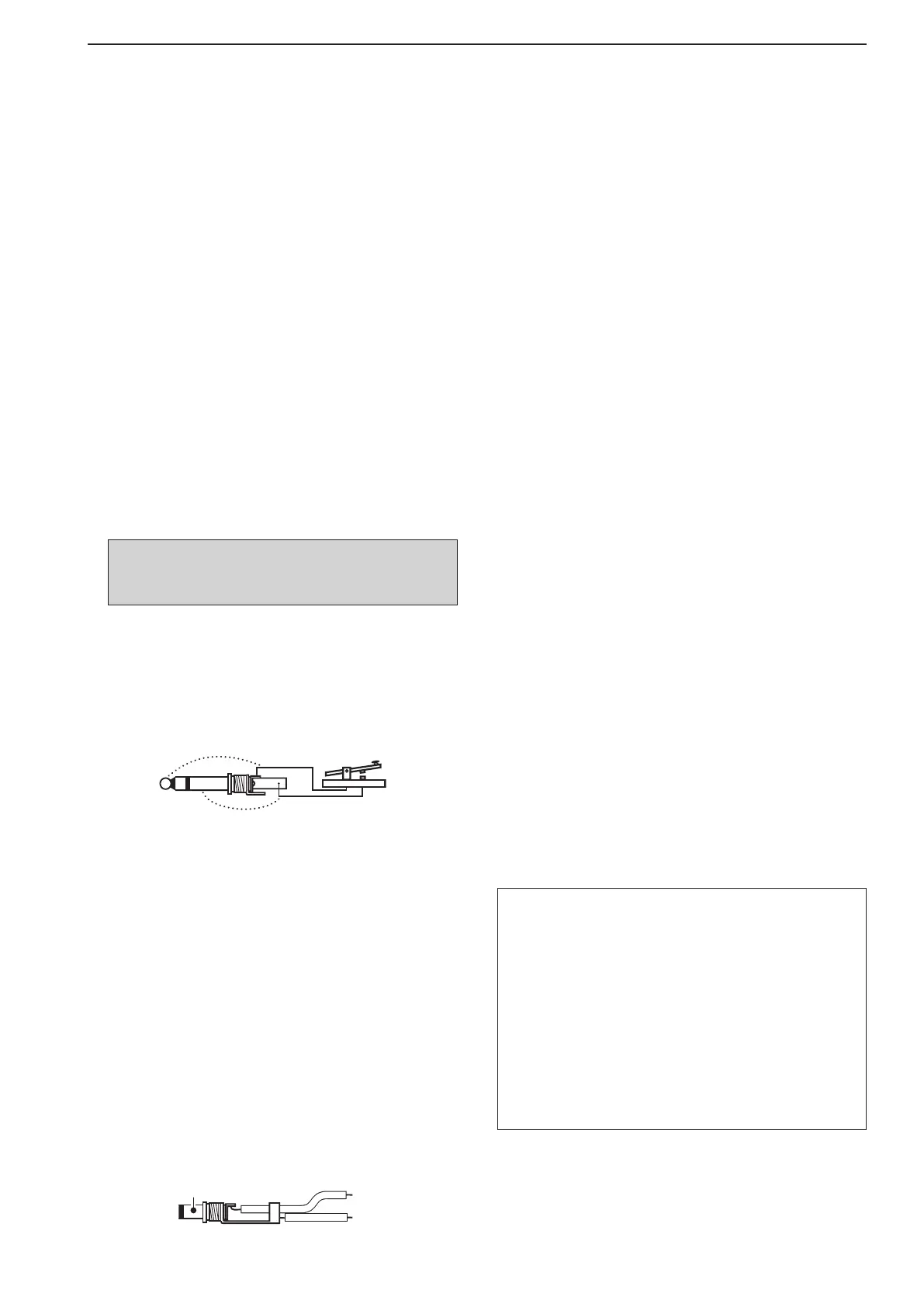
@3 STRAIGHT KEY JACK [KEY] (p. 2-4)
Accepts a straight key or external electronic keyer
with
1
⁄4 inch standard plug.
•[ELEC-KEY] on the front panel can be used for a
straight key or external electronic keyer. Deactivate the
internal electronic keyer in keyer set mode. (p. 4-12)
@4 EXTERNAL KEYPAD JACK [EXT KEYPAD]
(p. 2-6)
Connects an external keypad for direct voice mem-
ory (p. 7-11), memory keyer (p. 4-8), RTTY memory
(p. 4-16) or PSK memory (p. 4-24) transmission.
Transceiver mute control line (both transmit and re-
ceive) is also supported.
@5 METER JACK [METER] (p. 2-6)
Outputs the receiving signal strength level signal,
transmitoutputpower,VSWR,ALC,speechcom-
pression,V
d or Id level for external meter indica-
tion.
@6 DC OUTPUT JACK [DC OUT] (p. 2-6)
Outputsaregulated14VDC(approximately)forex-
ternalequipment.Connectedinparallelwith13.8V
outputs of [ACC 1] and [ACC 2]. (max. 1 A in total)
@7 REFERENCE SIGNAL INPUT/OUTPUT
TERMINAL [REF I/O]
Inputs/outputs a 10 MHz reference signal.
@8 S/P DIF INPUT TERMINAL [S/P DIF– IN] (p. 2-6)
@9 S/P DIF OUTPUT TERMINAL [S/P DIF– OUT]
(p. 2-6)
Connects external equipment that supports S/P DIF
input/output.
#0 CI-V REMOTE CONTROL JACK [REMOTE]
(p. 2-5)
➥ Connects a PC via the optional CT-17
c i -v l e v e l
c o n v e r t e r for external control of the trans-
ceiver.
➥ Used for transceive operation with another Icom
CI-Vtransceiverorreceiver.
#1 RS-232C TERMINAL [RS-232C] (p. 2-5)
Connects an RS-232C cable, D-sub 9-pin to con-
nect the IC-7800 to a PC.
Can be used for remotely control the IC-7800 with-
out the optional CT-17, or for RTTY/PSK31 de-
coded signal output. The [RS-232C] interface is
wired as a modem (DCE).
#2 KEYBOARD CONNECTOR [KEYBOARD]
(p. 2-6)
Connects a USB (Universal Serial Bus) device that
is a keyboard, mouse, hub or memory (USB flash
drive).
#3 EXTERNAL DISPLAY TERMINAL
[EXT-DISPLAY] (p. 2-6)
Connects to an external display monitor.
•Atleast800×600 pixel display is necessary.
#4 ETHERNET CONNECTOR [LAN] (p. 16-6)
Connects to a PC network through a LAN (Local
Area Network).
1
PANEL DESCRIPTION
NOTE: T/R control voltage and current must be
lowerthan16VDC/0.5A(or250VAC,
200 mA with MOS-FET switching).
About the [KEYBOARD] connector:
•SupportedonlyUSBflashdrive,keyboard,mouse
or hub.
•KEEP the transceiver power OFF when connecting
or disconnecting a USB keyboard, mouse or hub.
•DO NOT connect the following devices:
- Two or more the same kind of USB devices.
(Example: Two USB hubs or two USB mouses)
- Multimedia adapter
- USB HDD
- Larger than 32 GB USB flash drives
- Bluetooth
®
keyboard or mouse.