2-10
2
INSTALLATION AND CONNECTIONS
■ Microphones (options) (continued)
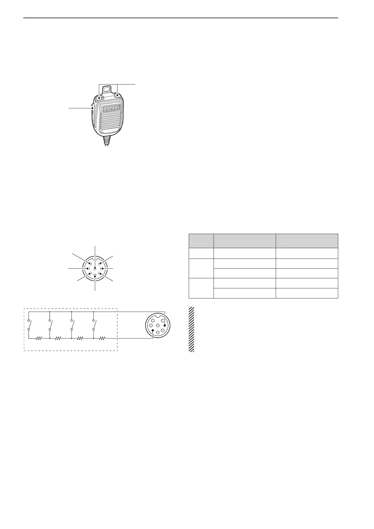
q PTT SWITCH
Hold down to transmit; release to receive.
w UP/DOWN SWITCHES [UP]/[DN]
Change the selected readout frequency or memory
channel.
•Holding down continuously changes the frequency or
memory channel number.
•Whileholdingdown[XFC],thetransmitreadoutfrequen-
cy can be controlled while in the split frequency mode.
•The[UP]/[DN]switchcansimulateakeypaddle.Preset
in the keyer set mode. (p. 4-12)
■ Microphone connector information
(Front panel view)
y GND (PTT ground)
t PTT
r Main readout squelch switch
q Microphone input
w +8 V DC output
e Frequency up/down
u GND
(Microphone ground)
i Main readout AF output
(varies with [AF])
CAUTION:
DO NOT short pin 2 to ground as this can damage
theinternal8Vregulator.
DC voltage is applied to pin 1 for microphone op-
eration. Use caution when using a non-Icom
microphone.
[MIC]
FUNCTION DESCRIPTION
Pin No.
w +8VDCoutput Max.10mA
e
Frequency up Ground
Frequency down Ground through 470 Ω
r
Squelch open “Low” level
Squelch closed “High” level
1.5 kΩ
±5%
1.5 kΩ
±5%
2.2 kΩ
±5%
4.7 kΩ
±5%
S1
(T1/M1/
PT1/RT1)
S2
(T2/M2/
PT2/RT2)
S3
(T3/M3/
PT3/RT3)
S4
(T4/M4/
PT4/RT4)
• EXTERNAL KEYPAD connection
To pin e
Microphone
connector
To pin y