2-2
■ Unpacking
After unpacking, immediately report any damage to
the delivering carrier or dealer. Keep the shipping car-
tons.
For a description and a diagram of accessory equip-
ment included with the IC-7800, see ‘Supplied acces-
sories’ on p. iii of this manual.
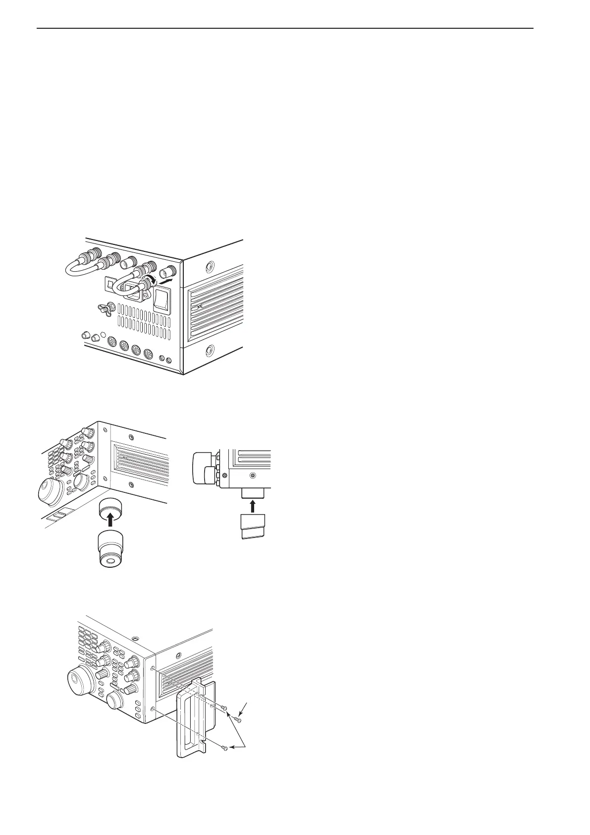
■ Antenna jumper cable connection
Connect the supplied coaxial cable (terminated with
BNC connectors) between [RX ANT A— IN] and [RX
ANT A— OUT], and, [RX ANT B— IN] and [RX ANT
B— OUT], respectively.
When connecting an external filter unit, pre-amplifier,
etc., connect the unit between [RX ANT A/B— IN] and
[RX ANT A/B— OUT] connectors.
■ Selecting a location
Select a location for the transceiver that allows ade-
quate air circulation, free from extreme heat, cold, or
vibrations,andawayfromTVsets,TVantennaele-
ments, radios and other electromagnetic sources.
The base of the transceiver has an adjustable stand
for desktop use. Set the stand to one of two angles de-
pending on your operating preference.
■ Rack mounting handle attachment
Remove the four screws from both sides of the front
panel and the two screws from both sides of the side
panel, then attach the rack mounting handles to the
sides of the transceiver using the supplied screws.
2
INSTALLATION AND CONNECTIONS