80
9
9
CONNECTIONS AND INSTALLATION
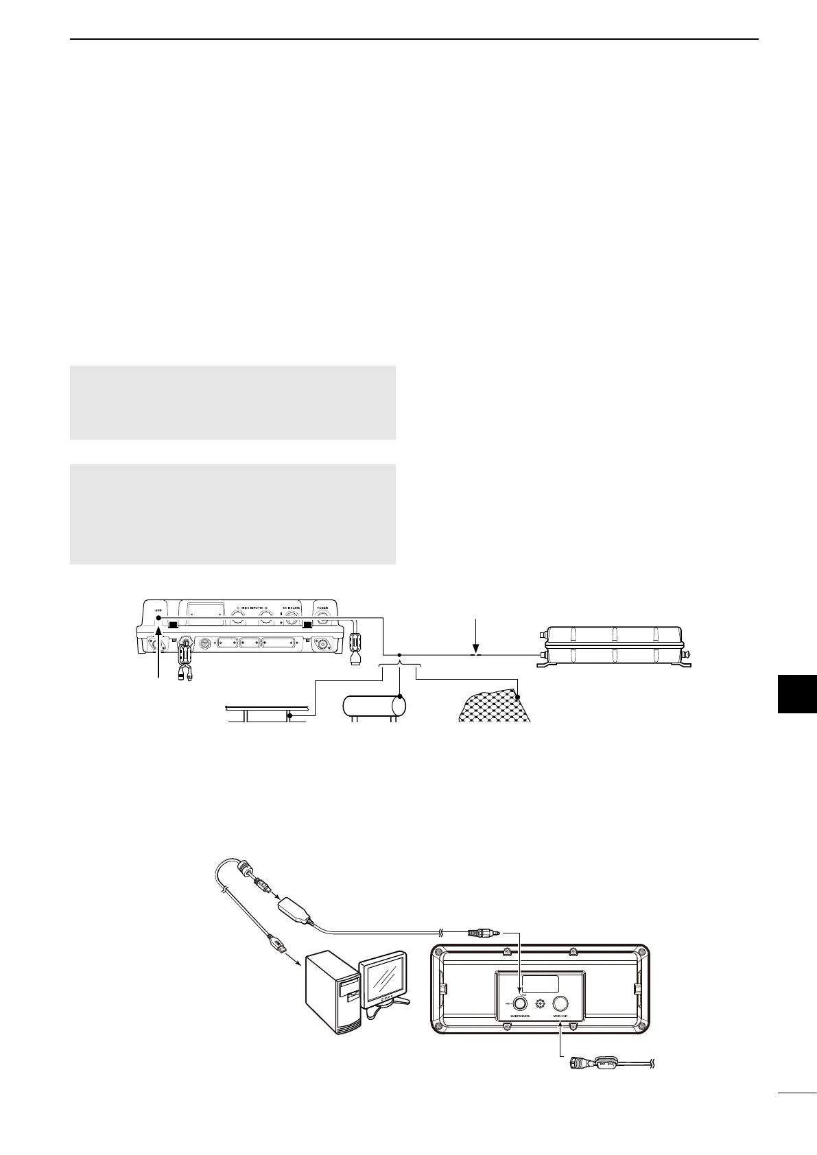
■ Ground connection
The transceiver and antenna tuner must have an
adequate RF ground connection. Otherwise, the
ef ciency of the transceiver and antenna tuner may
be reduced. Also, electrolysis, electrical shocks and
interference from other equipment may occur.
For the best results, use a 50 or 75 mm wide copper
strap, and make the connection as short as possible.
Ground the transceiver and antenna tuner to one
ground point, otherwise the voltage difference (at the
RF level) between the 2 ground points may cause
electrolysis.
RWARNING! When grounding to a metal hull
Use Zinc anodes to protect the hull from
electrolysis. Ask your dealer or installer for RF
grounding details.
CAUTION:
• NEVER connect the transceiver to a “positive-grounded
ship,” otherwise the transceiver will not function.
• Any external units, such as PC, printer and so on, must
be properly grounded. We suggest using a wide copper
strap.
Best ground points
• External ground plate
• Copper screen
• Copper foil
Acceptable ground points
• Stainless steel stanchion
• Through mast
• Through hull
• Metal water tank
Undesirable ground points
• Engine block
• Ship’s DC battery ground
Unusable ground points
(these connections may cause an explosion or
electrical shock)
• Gas or electrical pipe
• Fuel tank or oil catch pan
Copper pipe Metal object Copper screen
Wide Copper strap
Ground system example
■ Software maintenance
The Icom customer support center provides the
rmware le for transceiver maintenance. You can
update the transceiver’s rmware through a PC.
GND
GND
OPC-478UC
To the [MAINTENANCE]
connector
To the [MAIN UNIT]
connector
To the main unit
Remote control cable
Remote controller
To a USB port
PC