85
2001 NEW 2001 NEW
CONNECTIONS AND INSTALLATION
9
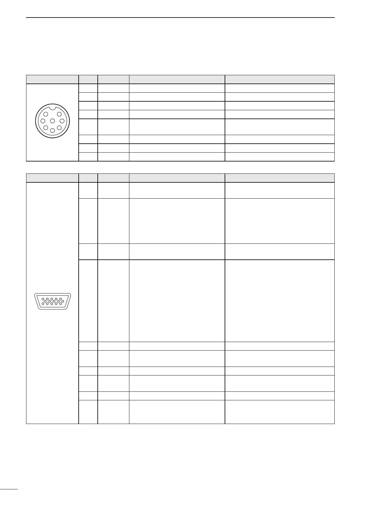
MICROPHONE Pin Pin name Description Specication
1 MIC (+) Audio input from the mic element. Input impedance: 2.4 kΩ
2 MIC SW Key detection. –
3 AF1 AF output controlled by [VOL]. –
4 AF2 Ground for AF1. –
5 PTT
PTT switch input.
Transmits when grounded.
–
6 GND Connected to ground. –
7 MIC (–) Coaxial ground for MIC (+). –
8 AF (–) Coaxial ground for AF1 and AF2. –
Front panel view
■ Connector information
AF/MOD Pin Pin name Description Specication
15
1115
1~4 NC
NOTE: Do not connect to these
pins.
–
5 DSSW
Remote alarm input
When connected to GND, the
transceiver sends a Distress call.
Can be used as an external
Distress switch.
–
6, 7 NC
NOTE: Do not connect to these
pins.
–
8 DSLD
Remote alarm output
Connect external equipment such
as a lamp or buzzer that needs a
power source, between this pin
and GND.
When receiving a Distress call*,
the key backlight blinks and
the internal relay intermittently
connects between this pin and
GND.
Applicable voltage: Less than 30 V
Current ow: Less than 1 A
9, 10 GND Ground –
11 MOD (+)
Modulation input from an external
unit for the SSB.
Input impedance: 600 Ω
Input level: Approximately 0.77 V rms
12 MOD (–) Coaxial ground for MOD (+). Input impedance: 600 Ω
13 AF (+)
AF detector output for an external
unit for SSB.
Output impedance: 600 Ω
Output level: 0.25 ~ 2.5 V rms
14 AF (–) Coaxial ground for AF (+). Output impedance: 600 Ω
15 SEND
Transmission control line for an
external unit for SSB (transmits
when grounded).
Output level: –0.5 ~ 0.8 V
Input level: Less than 20 mA
Front panel view
* A DSC call that is related to “Distress” as described below
• Distress call
• Distress acknowledgement
• Distress Relay call
• Distress Relay acknowledgement
• Distress Cancel call
• DSC call whose category is “Distress”