86
2001 NEW
9
9
CONNECTIONS AND INSTALLATION
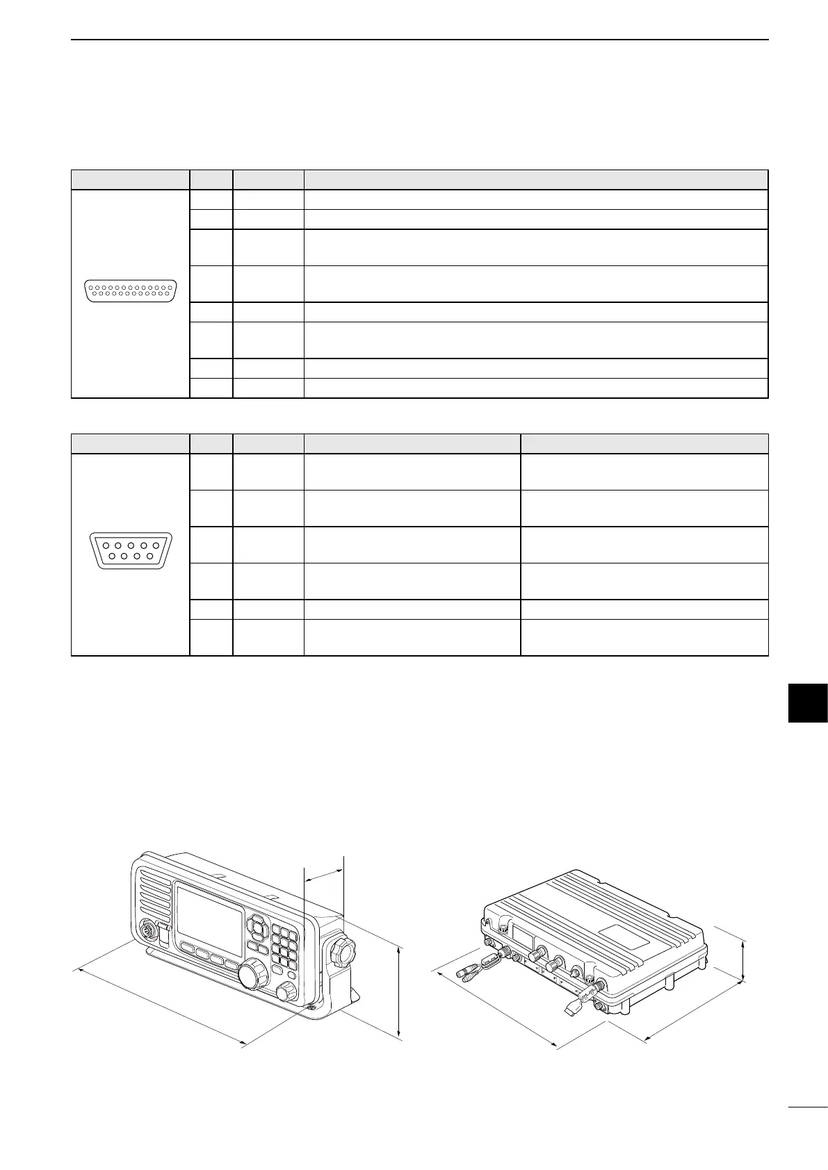
PRINTER Pin Pin name Description
13..........................1
25.......................14
1 STROBE Outputs a strobe pulse after data output.
2~9 DATA1~8 Outputs 8 bit parallel data.
10 ACKNLG
Receives a ‘Low’ pulse from the printer when the printer can accept more
data.
11 BUSY
The printer sets this pin to ‘High’ when it can not accept data, such as
when the printer is ‘off line.’
12~14
NC NOTE: Do not connect to these pins.
15 ERROR
The printer sets this pin to ‘Low’ when an error occurs, such as when the
printer has no paper.
16~17
NC NOTE: Do not connect to these pins.
18~25
GND Ground terminals.
REMOTE Pin Pin name Description Specication
15
69
1
DATA-
OUT (–)
Ground for DATA-OUT (+)
terminal.
–
2
DATA-
OUT (+)
IEC61162-1 Ed.4 (2010-11)
data output.
Input level: 5V, 40mA maximum
(at 2 V applied)
3
DATA-IN
(+)
IEC61162-1 Ed.4 (2010-11)
data input.
Output level: Less than 2 mA
(RS-422A balanced type)
4
DATA-IN
(–)
Ground for DATA-IN (+) terminal. –
5 GND Connected to ground. –
6~9 NC
NOTE: Do not connect to these
pins.
–
■ Transceiver dimensions
274 mm
114 mm
86 mm
367 mm
260 mm
95 mm