81
2001 NEW 2001 NEW
CONNECTIONS AND INSTALLATION
9
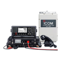
■ Power source
DC power cables
Ferrite EMI lter
The transceiver requires a regulated DC power
source of 26.4 V and at least 30 A.
Connect a transceiver directly to a 24 V battery in
your ship using the supplied DC power cable.
RWARNING! NEVER reverse the polarity when
connecting the transceiver to a DC power source.
This will damage the transceiver.
CAUTION: BE SURE to use a 24 V battery.
• Connecting the DC power cable
NOTE: Terminate the cable ends as illustrated
below.
+
_
• Attaching the weatherproof cap
Attach the supplied weatherproof cap for each
positive and negative line at the DC power terminal
as shown below.
• Attaching the DC power cable ferrite EMI lter
The DC power cables should be connected to the
transceiver’s main unit through the supplied ferrite
EMI lter, as shown below.
The ferrite EMI lter must be placed as near as
possible to the main unit.
black
Solder
24 V
battery
red Crimp
Supplied
DC power cable
Bend the
lug 90 degrees
Weatherproof
cap
■ Antenna
Most stations operate with a whip or long wire
antenna. However, those antennas cannot be
connected directly to the transceiver since their
impedance will not match the transceiver's impedance.
Use the AT-141 to connect antennas.
For details about antenna connections and installation,
see the supplied AT-141 Instruction manual.
RDANGER! HIGH VOLTAGE!
NEVER touch the antenna element or wire while
tuning or transmitting.
AT-141
Horizontal element
Vertical
element
Antenna
tuner
AT-141