89
2001 NEW 2001 NEW
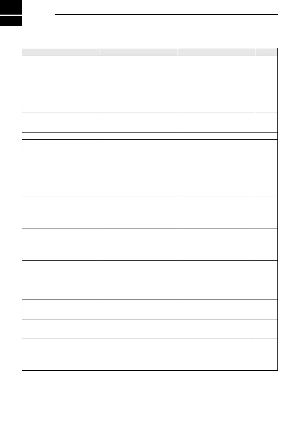
PROBLEM POSSIBLE CAUSE SOLUTION REF.
The transceiver does
not turn ON.
• Bad connection to the power
supply.
• Fuse is blown.
• Check the connection to the
transceiver and power supply.
• Find the cause, repair, then
replace the fuse.
p. 80
p. 86
Little or no sound comes from
the internal speaker.
• Squelch level is set too high.
• Volume level is set too low.
• The internal speaker is OFF.
• Set the squelch to the threshold
point.
• Set the volume to a suitable
level.
• Turn ON the internal speaker.
p. 15
p. 3
p. 5
You cannot transmit. • Some channels are set for
low power or receive only by
regulations.
• Change channels. p. 11
No beep sounds. • The Key Beep function is OFF. • Turn ON the Key Beep function. p. 77
The Main screen is not displayed
at power ON.
• MMSI (DSC self ID) code is not
set.
• Set the MMSI (DSC self ID)
code.
p. 8
Individual or Group ID
cannot be set.
• The entered ID code is
incorrect.
The st digit must be set to
between ʻ1ʼ and ʻ9ʼ for an
Individual ID.
The st digit must be set to ʻ0ʼ
for a Group ID.
• Enter a correct ID code. p. 23
“??” blinks instead of the position
data and time.
• 4 hours have passed after you
manually entered the position
data.
• The GPS position data is
invalid.
• Enter the current position data. p. 27
“NO POSITION” and “NO TIME”
are displayed instead of the
position data and time.
• A GPS receiver is not correctly
connected.
• The position data and time
have not been manually
entered.
• Check the GPS receiver
connection.
• Enter the current position data
and time.
p. 80
p. 27
Sensitivity is too low, and only
strong signals can be heard.
• The antenna is defective or
the coaxial cable connector is
shorted or cut.
• Repair the problem and then
reconnect to the antenna
connector.
p. 82
The communication cannot be
established
• The antenna is defective or
the coaxial cable connector is
shorted or cut.
• Repair the problem and then
reconnect to the antenna
connector.
p. 82
The received DSC call content is
not printed out.
• The printer is not correctly
connected, or the paper supply
is exhausted.
• Check the printer connection or
add paper.
p. 80
“The transceiver cannot receive
or transmit. Contact your dealer.”
is displayed.
• The transceiverʼs Phase Lock
Loop is unlocked.
• Contact your dealer. –
The transceiver is locked up, and
does not respond.
• A software error has occurred. –
( The transceiver will
automatically restart after
approximately 10 seconds has
passed.)
–
11
TROUBLESHOOTING