1
PANEL DESCRIPTION
1-4
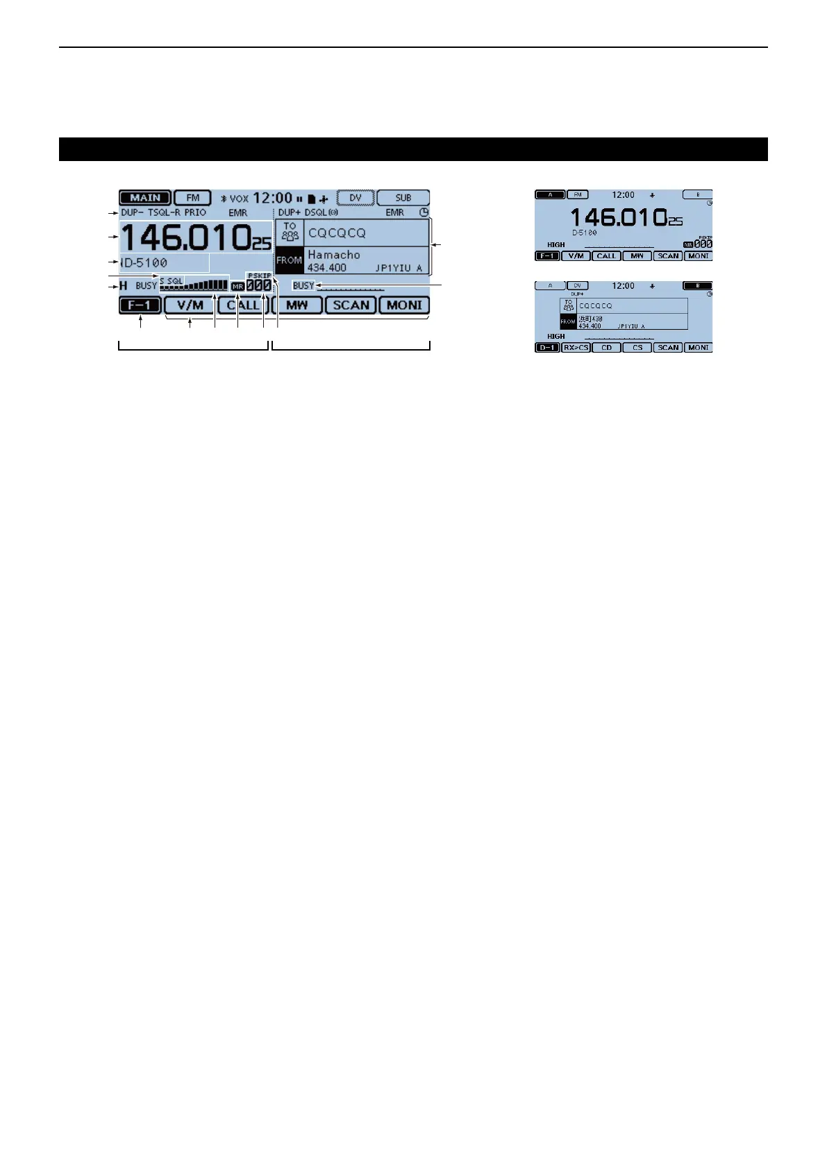
!3 DR SCREEN
Displays the DR screen where the D-STAR settings
are made.
!4BUSY/MUTEICON
“BUSY” is displayed while a signal is being re- ➥
ceived or the squelch is open.
“BUSY” blinks while the monitor function is acti- ➥
vated. (p. 2-8)
“MUTE” is displayed while the mute is activated. ➥
(p. 2-2)
!5 SKIP ICON (p. 4-7, p. 4-10)
Displays the selected Skip function.
• “SKIP”: Memory skip
• “PSKIP”: Program skip
!6MEMORYCHANNELNUMBER
Displays the selected Memory channel number, ➥
Memory Bank, and so on. (p. 2-9)
“ WX” is displayed when the Weather channel ➥
mode is ON.* (p. 2-9)
*Only the USA version transceiver.
!7 MEMORY ICON (p. 2-9)
Displayed when the Memory mode is selected.
!8 S/RF METER
Displays the relative signal strength of the receive ➥
signal. (p. 2-11)
Displays the output power level of the transmit ➥
signal. (p. 2-12)
!9 FUNCTION MENU DISPLAY (p. 1-5)
Displays the touch key, according to the selected
function menu group.
@0 FUNCTION GROUP ICON
Displays the selected function group (F-1 to F-4, D-1
to D-3) (p. 1-5)
@1 POWER ICONS
Displays the output power level of the transmit ➥
signal in three levels. (p. 2-12)
In the Dualwatch mode: ➥
“H” is displayed when you select high power.
“M” is displayed when you select mid power
“L” is displayed when you select low power.
@2 S-METER SQUELCH/ATTENUATOR ICONS
(p. 2-13)
“ S SQL” is displayed when the S-meter squelch ➥
is activated.
“ ATT” appears when the Attenuator function is ac- ➥
tivated.
@3 MEMORY NAME DISPLAY
In the Memory mode, displays the programmed
memory name. (p. 3-15)
@4 FREQUENCY READOUT
Displays the operating frequency. (p. 2-5)
@5 DUPLEX ICON
“DUP–” is displayed when minus duplex is selected,
and “DUP+” is displayed when plus duplex is select-
ed. (p. 11-4)
Controller — Display (Touch screen) (Continued)
@5
!3
!4
!9 !5!6!8 !7@0
@1
@2
@3
@4
Dualwatch mode Single watch mode (A band)
Single watch mode (B band)
This side becomes the A band
in the Single watch mode
This side becomes the B band
in the Single watch mode

 Loading...


