10 | Routine Operation INFICON
272 / 319 074-594-P1H Micro GC Fusion Operating Man-
ual
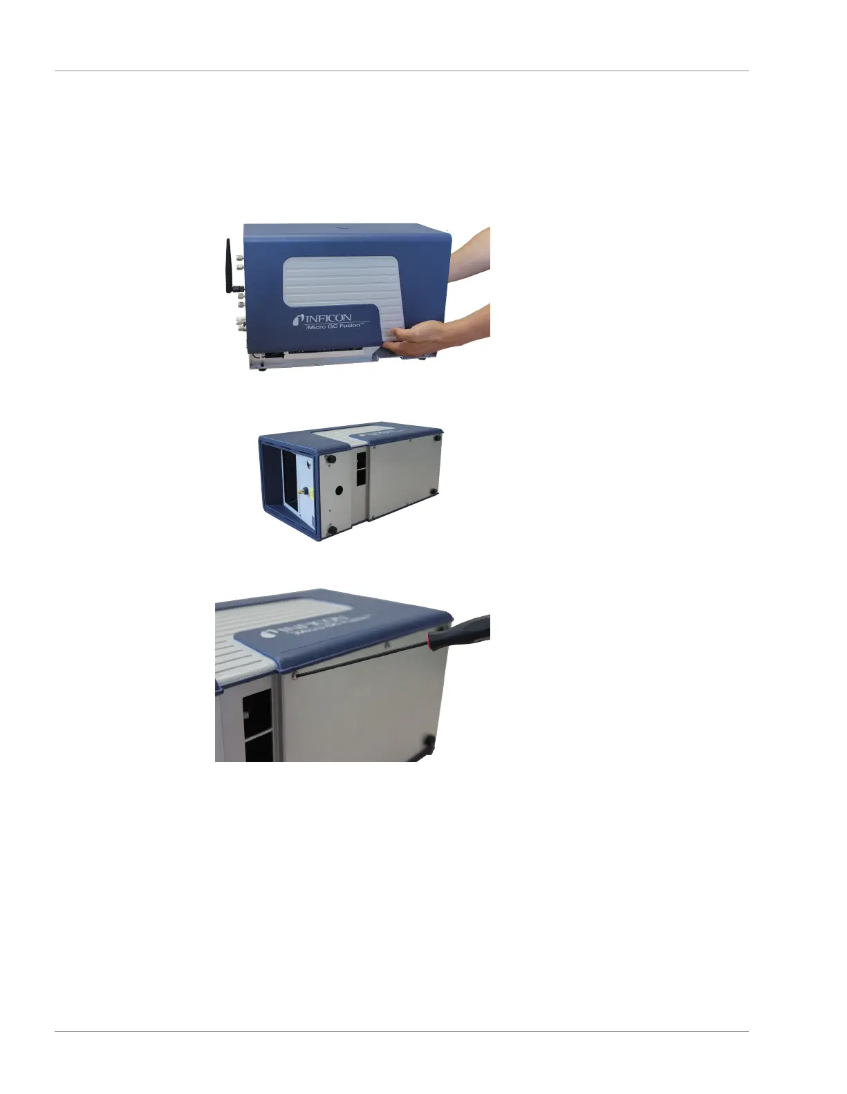
12
With finger tips, grasp the bottom of the housing cover and gently pull it apart.
Position the cover over Micro GC Fusion and lower it down over the housing to
replace the housing cover back on Micro GC Fusion.
13
Set Micro GC Fusion on its left side as shown.
14
Use a 2.5 mm ball-point hex driver to replace the eight bottom screws.
15
Return Micro GC Fusion to the upright position.
16
Connect the sample gas connection(s), carrier gas connections and venting
connections.
17
Connect the external electrical cables, including the power cable and the
Ethernet cable.
18
Power up the instrument by pressing the
On/Standby
button on the front panel.
Micro GC Fusion automatically recognizes the new or replacement module
configuration when it is turned on. The GC module configuration is stored in the
EEPROM located on the GC module interface circuit board.

 Loading...


