178 EasyCoder PX4i and PX6i Service Manual
Chapter 16 — Interfaces
Industrial Interface Configuration
The Industrial Interface provides:
• 8 digital IN ports with optocouplers (Opto In)
• 8 digital OUT ports with optocouplers (Opto Out)
• 4 OUT ports with relays (Relay Out)
The Industrial Interface has no straps or circuits to be fi tted or removed.
All signals are available on a DB-44pin socket and the various ports are
controlled by the Intermec Fingerprint instructions PORTIN and POR-
TOUT ON/OFF (see Intermec Fingerprint v8.xx, Programmer's Reference
Manual).
Digital Opto In
The status of the digital IN ports can be read using PORTIN functions. If
a current is led through the optocoupler of the port, PORTIN returns the
value -1 (true), else it returns the value 0 (false).
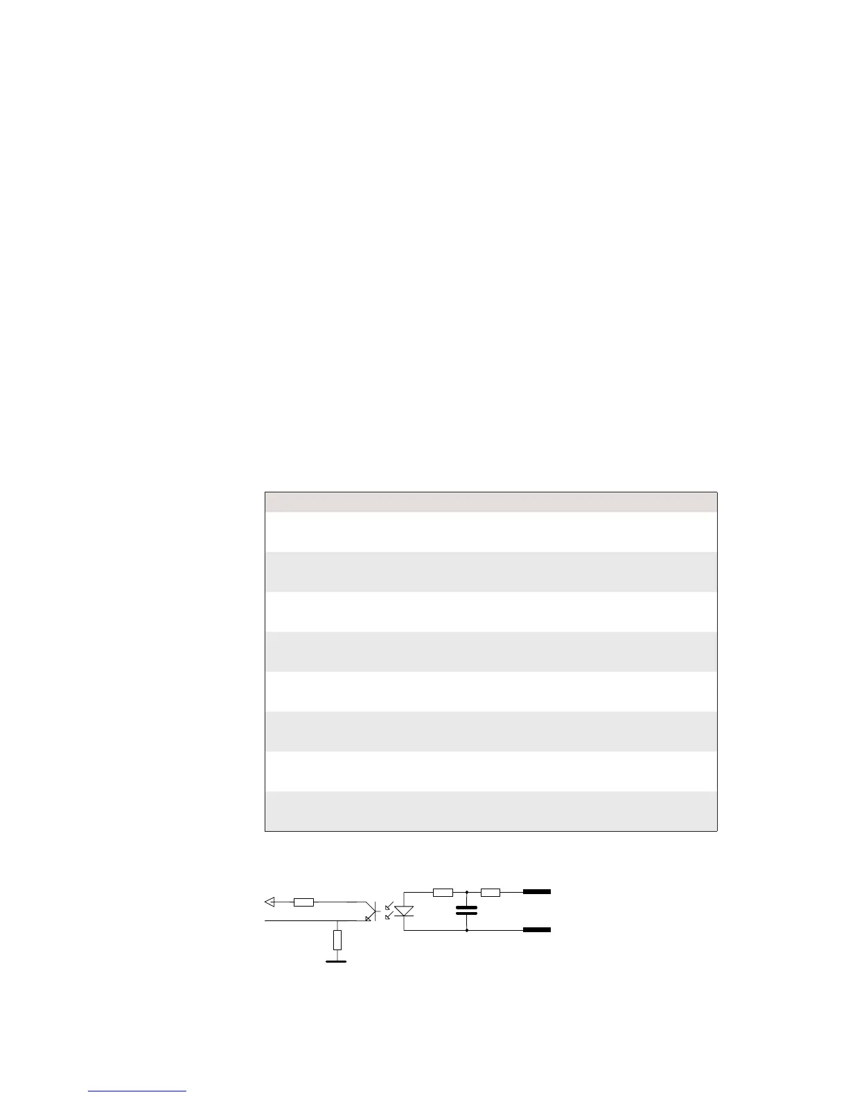
Signal Description Min. Typical Max.
Vin [High] Input Voltage High 10V 24V 40V
Vin [Low] Input Voltage Low -1V 0V 1V
Connector Configuration
The Fingerprint reference numbers inside the parentheses refer to a second
Serial/Industrial interface board.
Simplifi ed schematics of a digital IN port.
Pin Signal Name Description Fingerprint Ref. No.
10 IN1A Anode Opto In Channel 1 + 101 (301)
40 IN1K Cathode Opto In Channel 1 -
26 IN2A Anode Opto In Channel 2 + 102 (302)
11 IN2K Cathode Opto In Channel 2 -
41 IN3A Anode Opto In Channel 3 + 103 (303)
27 IN3K Cathode Opto In Channel 3 -
12 IN4A Anode Opto In Channel 4 + 104 (304)
42 IN4K Cathode Opto In Channel 4 -
28 IN5A Anode Opto In Channel 5 + 105 (305)
13 IN5K Cathode Opto In Channel 5 -
43 IN6A Anode Opto In Channel 6 + 106 (306)
29 IN6K Cathode Opto In Channel 6 -
14 IN7A Anode Opto In Channel 7 + 107 (307)
44 IN7K Cathode Opto In Channel 7 -
30 IN8A Anode Opto In Channel 8 + 108 (308)
15 IN8K Cathode Opto In Channel 8 -