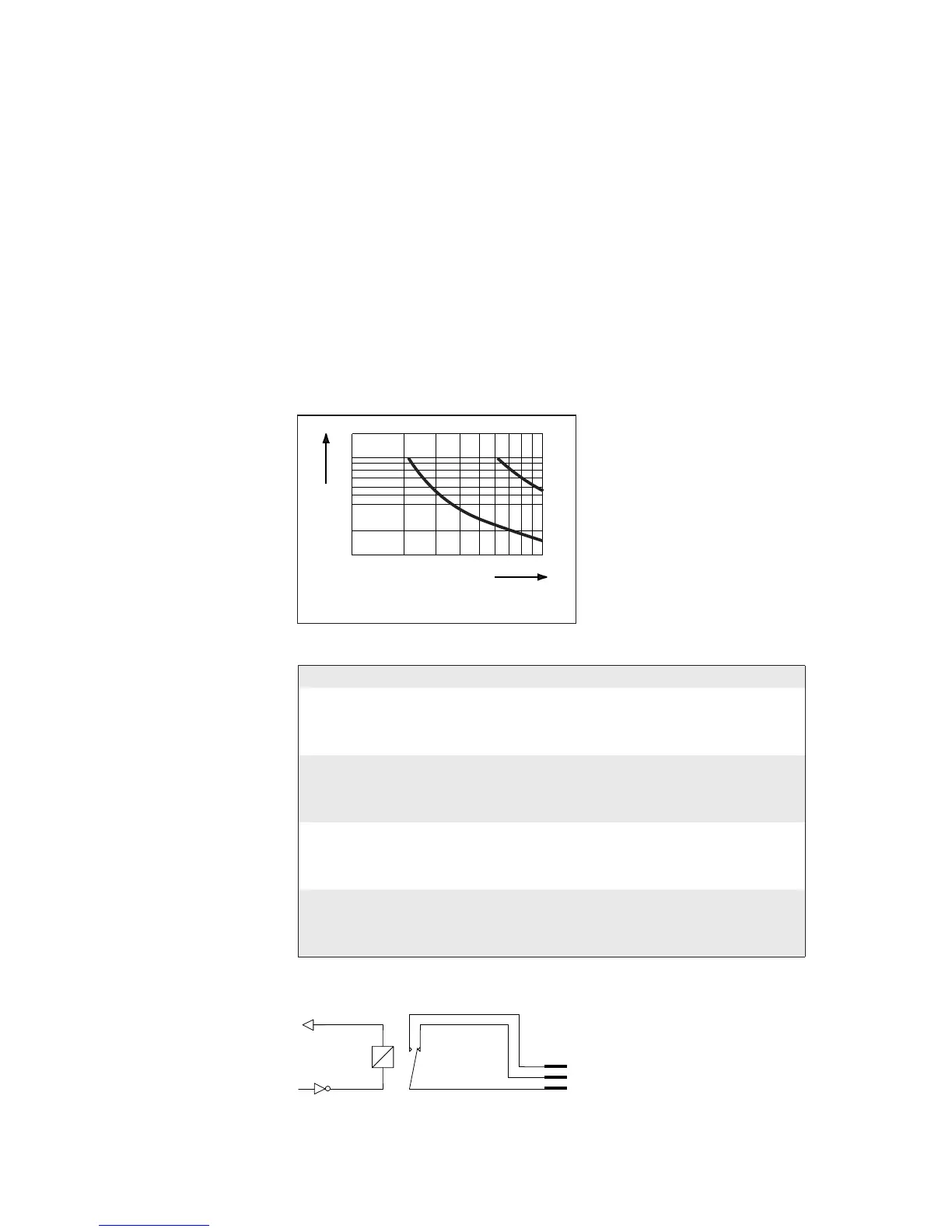
1
0.5
0.1
10 20 30 40 50 100
DC Voltage (VDC)
a: resistive load
b: inductive load L/R=20 ms
DC current (A)
a
b
VCC
REL com
REL nc
REL no
180 EasyCoder PX4i and PX6i Service Manual
Chapter 16 — Interfaces
Relay Out
The relays of the OUT ports can be individually activated using PORT-
OUT ON/OFF statements.
The status of the ports can be read by means of PORTIN functions. If a
relay is activated, PORTIN returns the value -1 (true), else it returns the
value 0 (false).
Max AC Load Breaking Capacity
Signal Description Max.
I Current 1A
Psw AC Switching power 100VA AC
Usw AC Switching voltage 100V AC
Max DC Load Breaking Capacity
Connector Configuration
The Fingerprint reference numbers inside the parentheses refer to a second
Serial/Industrial interface board.
Simplifi ed schematics of a relay OUT port.
Pin Signal Name Description Fingerprint Ref. No.
16 REL1nc Relay 1 Normally Closed 201 (401)
1 REL1no Relay 1 Normally Open
31 REL1com Relay 1 Common
17 REL2nc Relay 2 Normally Closed 202 (402)
2 REL2no Relay 2 Normally Open
32 REL2com Relay 2 Common
18 REL3nc Relay 3 Normally Closed 203 (403)
3 REL3no Relay 3 Normally Open
33 REL3com Relay 3 Common
19 REL4nc Relay 4 Normally Closed 204 (404)
4 REL4no Relay 4 Normally Open
34 REL4com Relay 4 Common