1.2. Operating Unisab III control
1.2.1 Start-up
On delivery all electrical components in the compressor are connected to Unisab III. On site it
is only necessary to add the correct supply voltage from the local installations. The electric
wiring must be carried out according to the wiring diagrams for Unisab III at the end of this
manual.
Note in particular that
• no outside voltage must be applied to the digital inputs of Unisab III.
• the supply voltage must be between 85 VAC and 250 VAC.
Before any voltage is applied to Unisab III, the emergency stop switch must be activa-
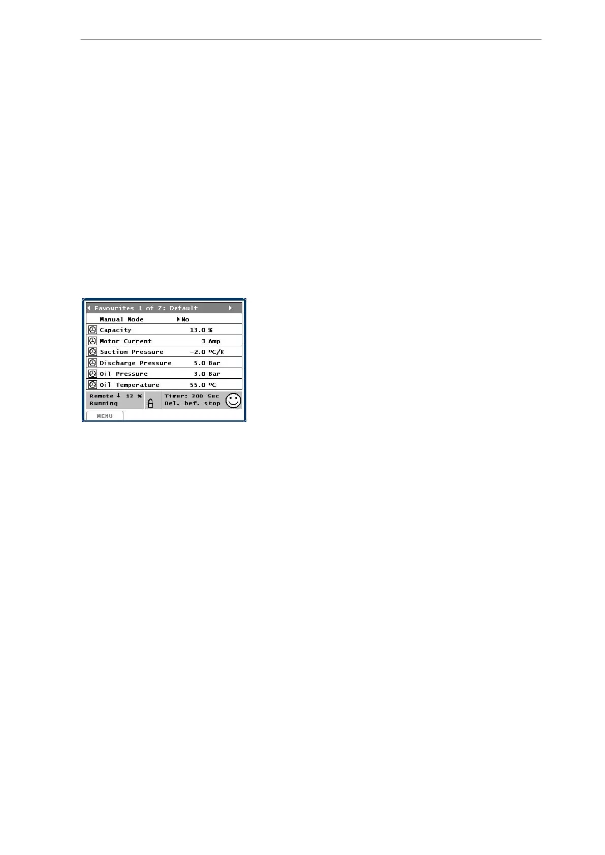
ted. When voltage is applied to Unisab III, the default picture shown below will appear in the
display and Unisab III will be ready for operation.
Fig. 1: Default picture
As Unisab III has been programmed with values for alarm limits, shutdown limits, set points,
etc., the compressor can be started immediately.
However, some of the values must be adapted to the actual operating situation. It is also rec-
ommended to read this manual carefully to acquire a thorough knowledge of how to operate
Unisab III.
Unisab III is operated exclusively by means of the front panel keys. Reading of operating con-
ditions as well as changing limiting values and set points is carried out via the display. The
display contains a number of different pictures.
The control panel is usually closed and locked with two screws at the bottom of the front pan-
el. When turning the screws, the front panel is loosened and can be lifted to an open position,
yet still fastened to the cabinet. See Fig. 2.
Unisab III control
14/319
Engineering manual - Unisab III 1.10
001930 en 2014.09
 Loading...


