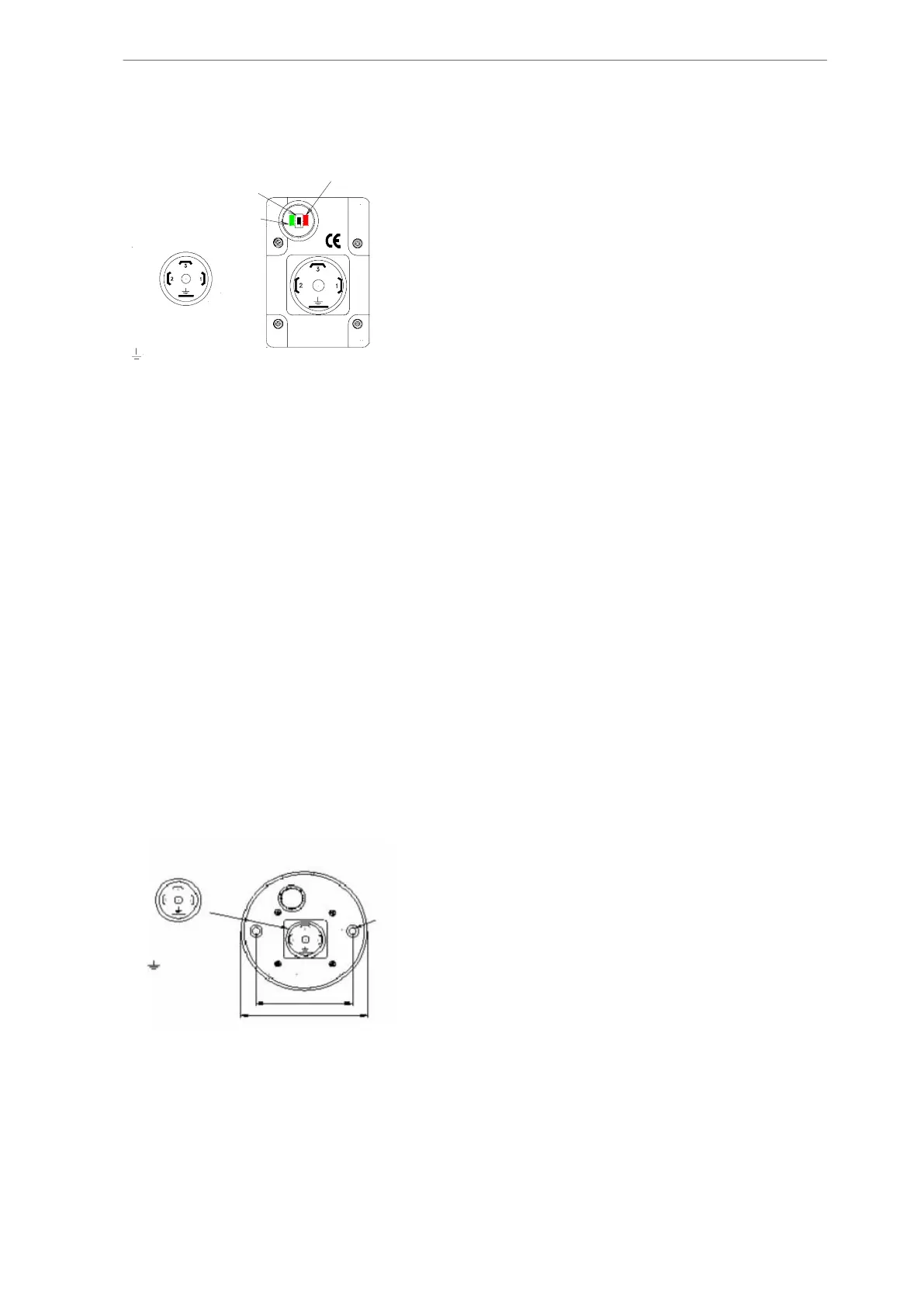
1
1 =
2 =
3 =
=
Supply, 24V DC
Common, 0V DC
Out, 4-20 mA
GND
Calibration
push button
LED supply
LED digital output
Plug connection
Fig. 33: Short-stroke
As shown in Fig. 33 the capacity transmitter is fitted with a single calibration button surroun-
ded by a green and red LED. During normal operation the red LED is flashing rather slowly.
The green LED is switched on constantly when the transmitter is in 100% position whereas it
flashes quickly when the transmitter is in 0% position.
Calibration is carried out as follows:
1. Apply supply voltage minimum five minutes before calibration.
2. Move the slide to its minimum position and press the calibration button once. The red
LED will switch ON. After a while, the red LED will turn OFF indicating that it is ready
for 100% calibration.
3. Move the slide to its maximum position and press the calibration button again. The
red LED will start flashing quickly. After a while the red LED will flash normally and
calibration is completed.
7.5.10 Adjusting long-stroke capacity rod for SAB 193-233-283 and SAB
355
Note: The transmitter cannot be calibrated. Software calibration in Unisab III must be used.
Terminal connection is shown in Fig. 34.
-- 1 --
Plug connection
Dia.
7 mm
60 mm
74 mm
1=Supply +10-32V DC
2=Common 0V DC
3=Out 4-20 mA
GND
Fig. 34: Terminal connection
Note: As the compressors are equipped with auto Vi, follow the instruction in subsection
7.5.4. Capacity slide adjustment, auto Vi and subsection 7.5.13.
Calibration
246/319
Engineering manual - Unisab III 1.10
001930 en 2014.09
 Loading...


