The signal must be scaled to fit the sensor measuring range. Ex.: A temperature sensor of
-30°C to +20°C is used.
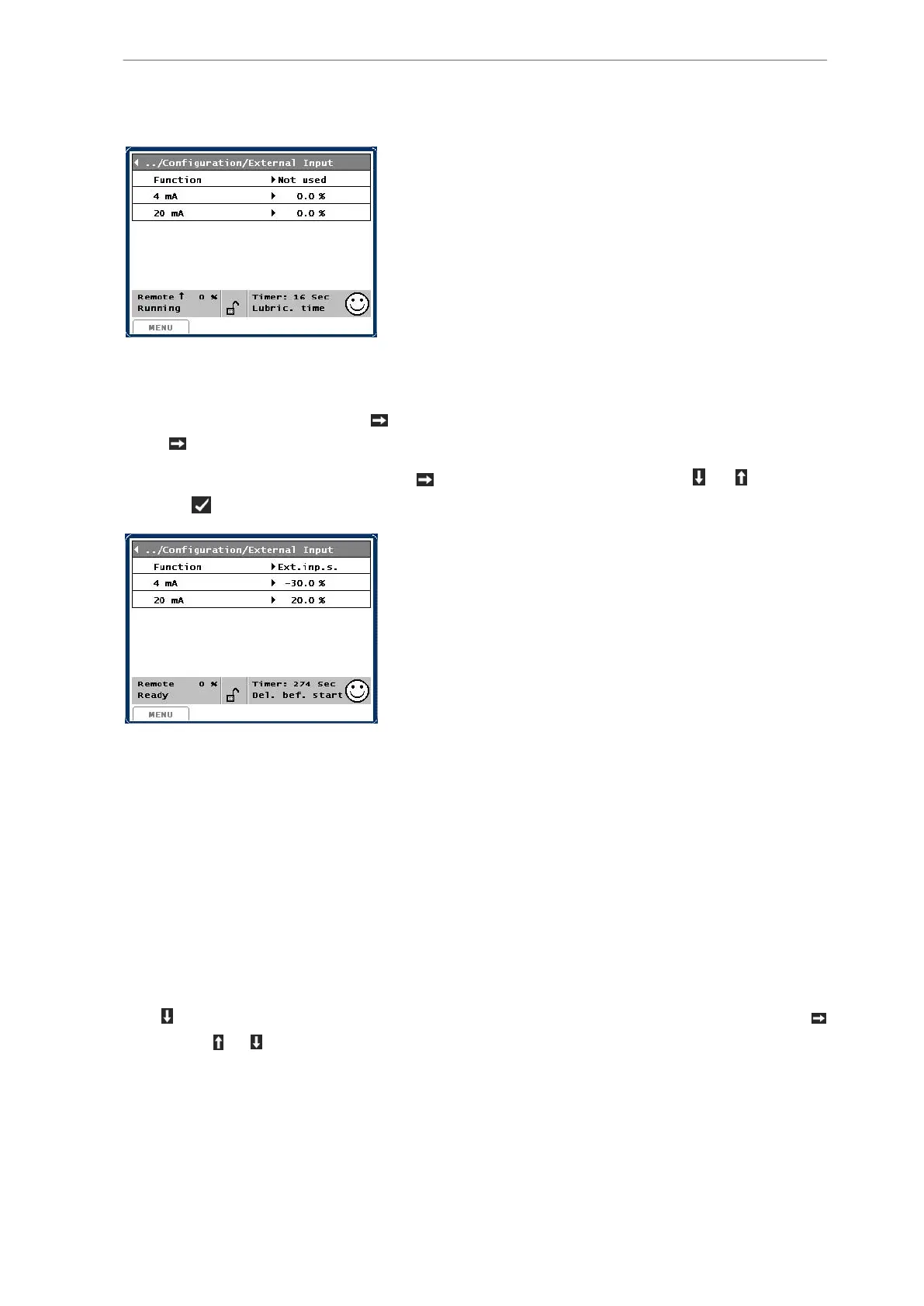
Move the cursor to 4 mA, press and change the value to -30. Move the cursor to 20 mA,
press
and change the value +20.
Move the cursor to second line, press
and select Ext. input signal with or . Finish by
pressing
. The picture will now look like this:
Each measuring signal can be scaled in accordance with the transducer measuring range.
In the menu Setup/Compr. Control, select one of the following in the Control on line:
Ext. cool
If selecting this function, the compressor will regulate the capacity upwards in case of increas-
ing measuring value.
Ext. heat
If selecting this function, the compressor will regulate the capacity upwards in case of de-
creasing measuring value.
Now select picture Control values/User/User input 1/Control. Go to the bottom of the picture
with where the set values of the regulator are positioned. These can be set by pressing
followed by or .
3.1.11 Set point control with user input 1
The actual set points of Suction pressure, Process out (Brine) temperature, Discharge pres-
sure, Process out (Hot Water) and Capacity can all be changed through the 4-20 mA User in-
put 1 signal. Connect these to the terminals as shown in the wiring diagrams.
Compressor control and surveillance
76/319
Engineering manual - Unisab III 1.10
001930 en 2014.09
 Loading...


