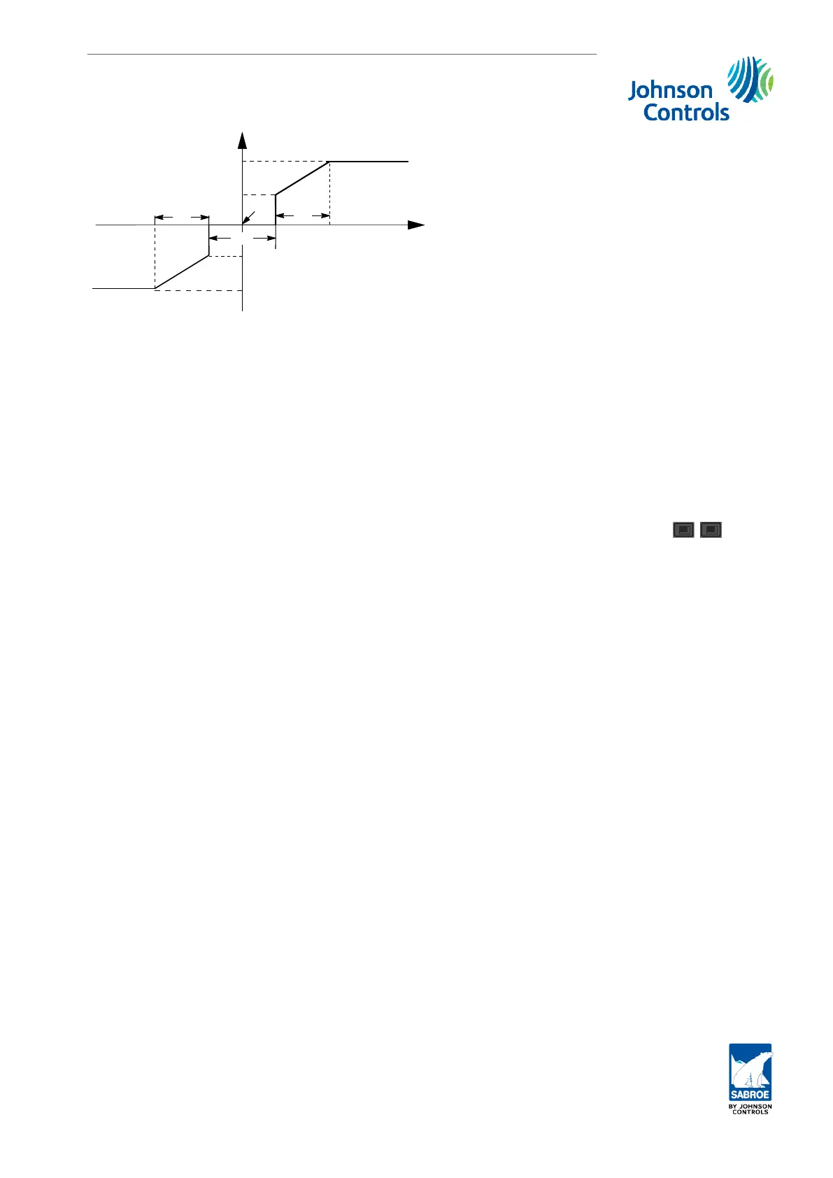
Rapidly up
Very slowly up
P. Band
SP
NZ
Very slowly down
Rapidly down
Error signal
P. band
Fig. 13: Regulation principle
3.1.3 Regulation of screw compressors
Screw compressors are capacity regulated (hydraulically or electrically) by moving the capaci-
ty slide. This takes place via two digital outputs, which are controlled by Unisab III, so that
the slide moves towards max. or min. capacity according to demand. The setting is stepless
from 0 to 100%. Unisab III will usually pulse the digital outputs with a pulse/delay ratio. Con-
sequently, a constant up or down signal will rarely be given.
The capacity control must be seen as two PID control loops (an inner and an outer loop). The
inner loop, which is a proportional regulator, adjusts the slide position continuously according
to the capacity set point. In Manual mode the capacity set point is selected with the
F2
/
F3
keys and in Auto/Remote mode it is selected automatically by the outer loop. As long as this
set point is constant, the inner loop will ensure that the capacity slide remains in this position
independent of any other outside influences.
The outer loop, which can be a PID or I regulator, adjusts the capacity set point according to
the selected control set point and measured value, e.g. the suction pressure set point and
measured value. In Manual mode, the outer loop is not active. In Auto and Remote, the outer
loop is active according to the Control on setting. See subsection 3.1.2. Regulator set-up.
The inner loop set point can also be controlled via the external input (see subsection
3.1.12. Capacity control with user input 1) or via the communication network.
3.1.4 Capacity PID regulation (outer loop)
On screw compressors a PID regulator is used for the outer loop of capacity regulation. In the
picture Setup/Compr.Control it is possible to select Capacity Controller = PID or I. If PID is
selected, all the parameters stated below are accessible.
If I is selected only the parameters Actual set point, Set point 1 and 2, Neutral zone and Prop.
band are accessible. The actual parameters are found in the relevant picture, e.g. Control val-
ues/Suction/Pressure/Control. Each parameter is briefly described below. The theory behind
PID regulation is described in innumerable books about automatic regulation. These books al-
so describe methods for optimising the parameters.
Compressor control and surveillance
Engineering manual - Unisab III 1.10
001930 en 2014.09
65/319
 Loading...


