Name Description
Actual Sp The set point the PID controller is currently working with
Set point 1 User selected set point 1
Set point 2 User selected set point 2
Neutral zone The neutral zone is a symmetrical area around Actual set point.
When the controlled value is inside the area, the controller will be
passive. The purpose is to increase service life of the output hard-
ware (relays, valves, spindle motor, etc). However, this is also
partly ensured by the parameter Min pulse, see 3.1.5. Capacity P
regulation (inner loop) below, which is why the Neutral zone can be
set at 0. An increased Neutral zone makes regulation less accurate.
Prop. band The proportional band determines the total gain in the control loop.
Increasing Prop. band provides a slower response. Thus changing
Prop. band does not only affect the proportional term, but also the
integral and differential terms.
T. int. Integral Time determines the gain of the integral term. A small T.
int. means a large gain, i.e. the controller will try to reach the set
point faster.
T. diff. Differential Time determines the gain of the differential term. A
large T. diff. means a large gain. Normally, select T. diff. = 0 which
deactivates the differential term and makes the regulator work as
a PI controller.
P. part This field shows the actual Proportional term calculated by the PID
controller.
I. part This field shows the actual Integral term calculated by the PID con-
troller.
D. part This field shows the actual Differential term calculated by the PID
controller
Reg. output The actual Regulator output is the sum of P. part, I. part and D.
part.
Table 18: Description of regulating parameters
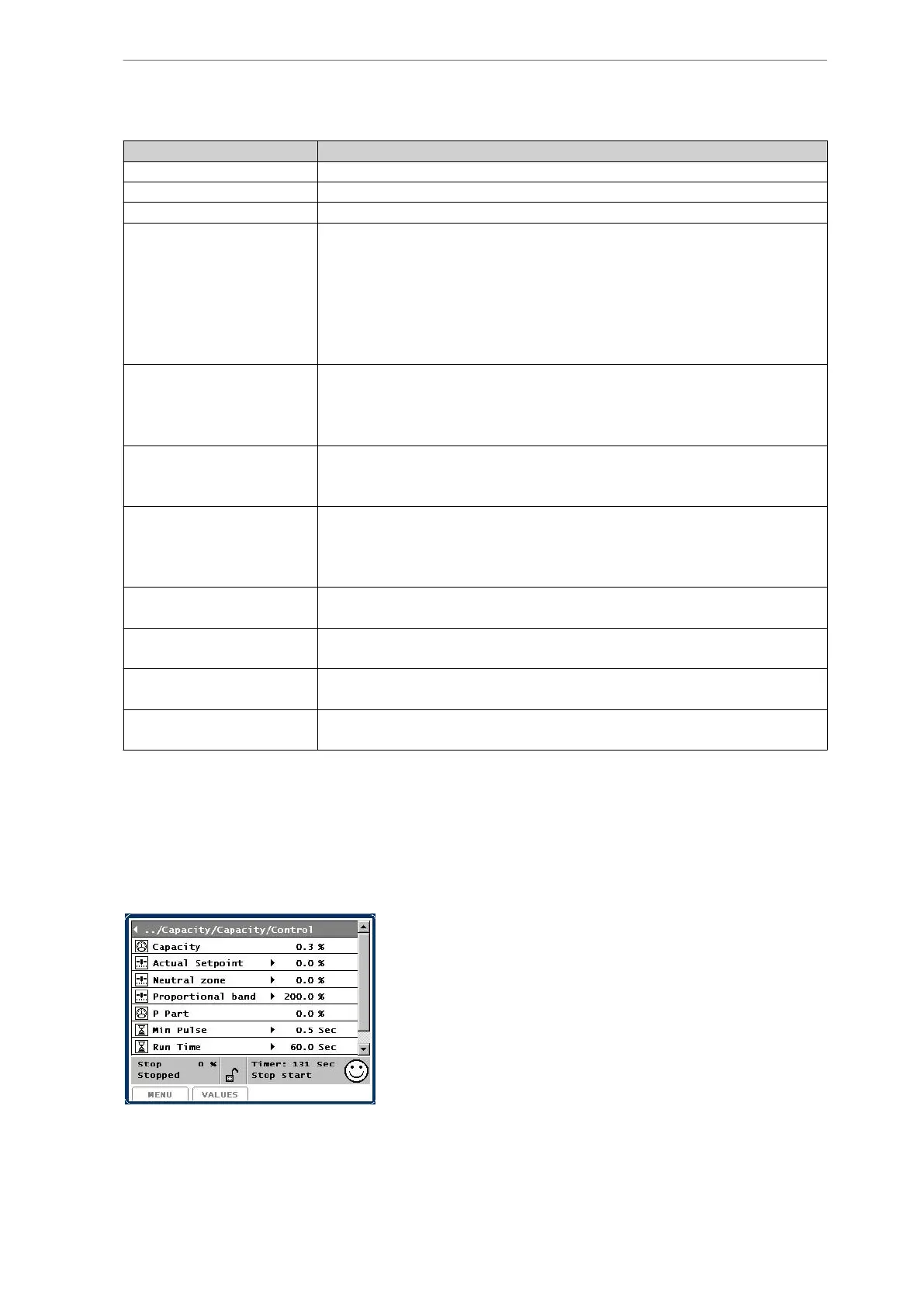
3.1.5 Capacity P regulation (inner loop)
The parameters for the inner loop, which is only a proportional regulation (P regulator), are
set in the picture Control values/Capacity/Capacity/Control. The P regulator parameters in-
clude Actual Set point, Neutral zone, Proportional band and P Part. Actual set point is the ca-
pacity set point generated by the outer loop.
Additionally the following parameters can be selected:
• Min Pulse is the shortest pulse given by Unisab III on the relay output. E.g. it takes
time for a hydraulic valve to open and close and for the hydraulic oil to move so a
pulse shorter than about half a second would have no effect and would only shorten
Compressor control and surveillance
66/319
Engineering manual - Unisab III 1.10
001930 en 2014.09
 Loading...


