7.5.8 Adjusting long-stroke capacity rod for SAB 283 Mk1
For type part no. 1373-038
Note: For long-stroke transmitters with part no. 1373-057 calibration and terminal connec-
tion are similar to that of SAB 110, SAB 128 etc. Please see subsection 7.5.7.
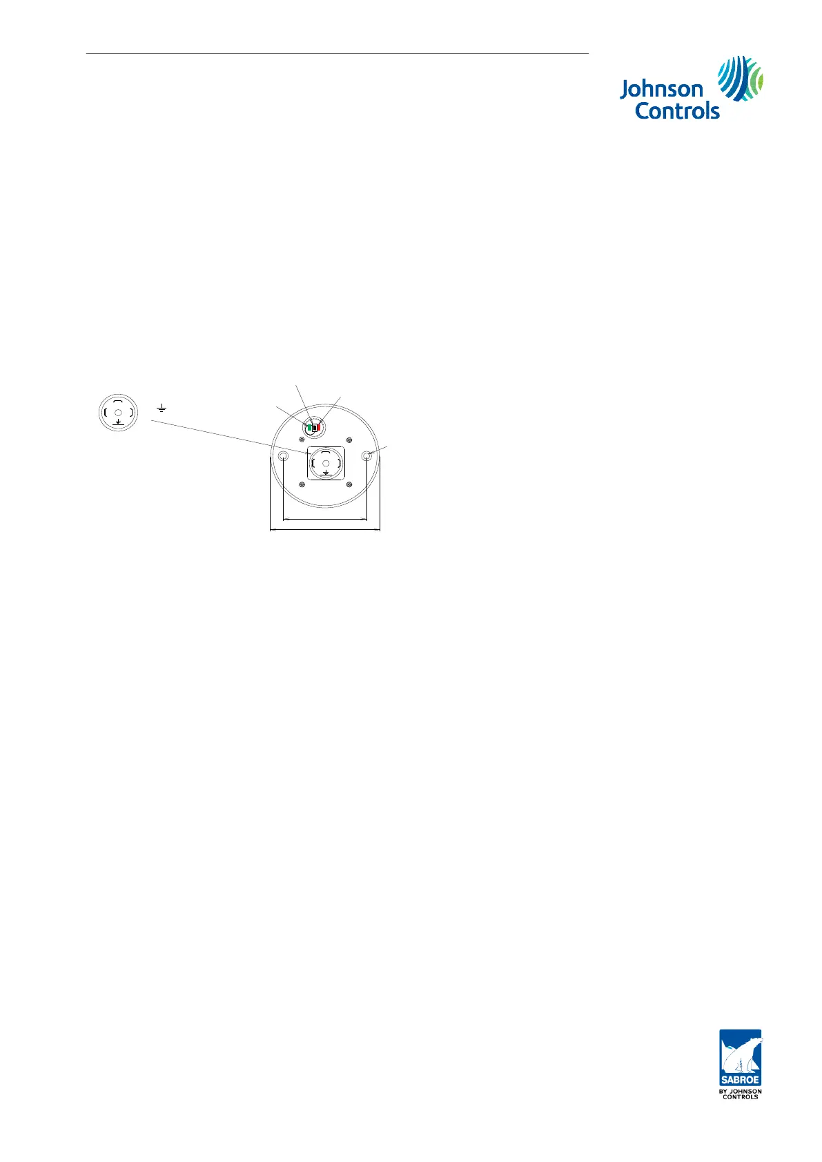
As shown in Fig. 32, the capacity transmitter is fitted with a single calibration button surroun-
ded by a green and red LED.
During normal operation the red LED flashes rather slowly. The green LED is switched on con-
stantly when the transmitter is in 100% position whereas it flashes quickly when the transmit-
ter is in 0% position.
3
2
1
2 =
1 =
3 =
3
74mm
60mm
2
1
Plug connection
Supply, +10 to 32V DC
Common, 0V DC
Out, 4-20 mA
GND
LED digital
output (option)
Calibration
push button
LED supply/operation
Dia
7 mm
Fig. 32: Long-stroke SAB 283 Mk1
Calibration is carried out as follows:
1. Apply supply voltage minimum five minutes before calibration.
2. Move the slide to minimum position and press the calibration button once. The red
LED will switch ON. After a while, the red LED will turn OFF indicating that it is ready
for 100% calibration.
3. Move the slide to its maximum position and press the calibration button again. The
red LED will start flashing quickly. After a while the red LED will flash normally and
calibration is completed.
7.5.9 Adjusting short-stroke capacity rod for Gram GST, GSV and RWF
and short-stroke volume transmitter for GSV, RWF and SAB 283 Mk1 and
SAB 355 Mk1
For part no. 1373-037
Note: For short-stroke transmitters with part no. 1373-061 calibration and terminal connec-
tion are similar to that of SAB 100, SAB 128 etc. Please see subsection 7.5.7.
Calibration
Engineering manual - Unisab III 1.10
001930 en 2014.09
245/319
 Loading...


