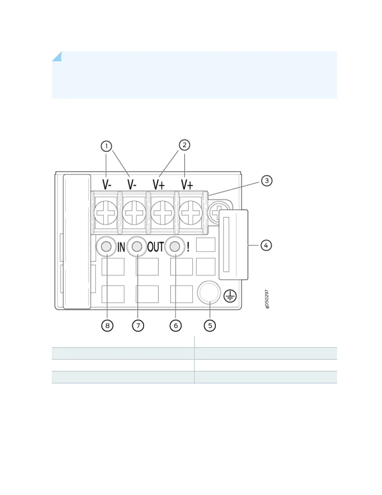
NOTE: The DC power supply in the switch has four terminals labeled V-, V-, V+, and V+ (see
Figure 20 on page 36) for connecng DC power source cables labeled posive (+) and
negave (–).
Figure 20: DC Power Supply Faceplate in EX4600 Switches
1—
Feed B input terminals
5—
ESD grounding point
2—
Feed A input terminals
6—
Fault LED
3—
Terminal block
7—
Output LED
4—
Ejector lever
8—
Input LED
To supply sucient power, terminate the DC input wiring on a facility DC source that is capable of
supplying a minimum of 7 A at –48 VDC.
To avoid electrical injury, carefully follow instrucons in "Installing a Power Supply in an EX4600 Switch"
on page 100 and "Removing a Power Supply from an EX4600 Switch" on page 98.
36