c. Tighten the screws on the power supply terminals unl snug using the screwdriver. Do not
overghten—apply between 5 in-lb (0.56 Nm) and 6 in-lb (0.68 Nm) of torque to the screws.
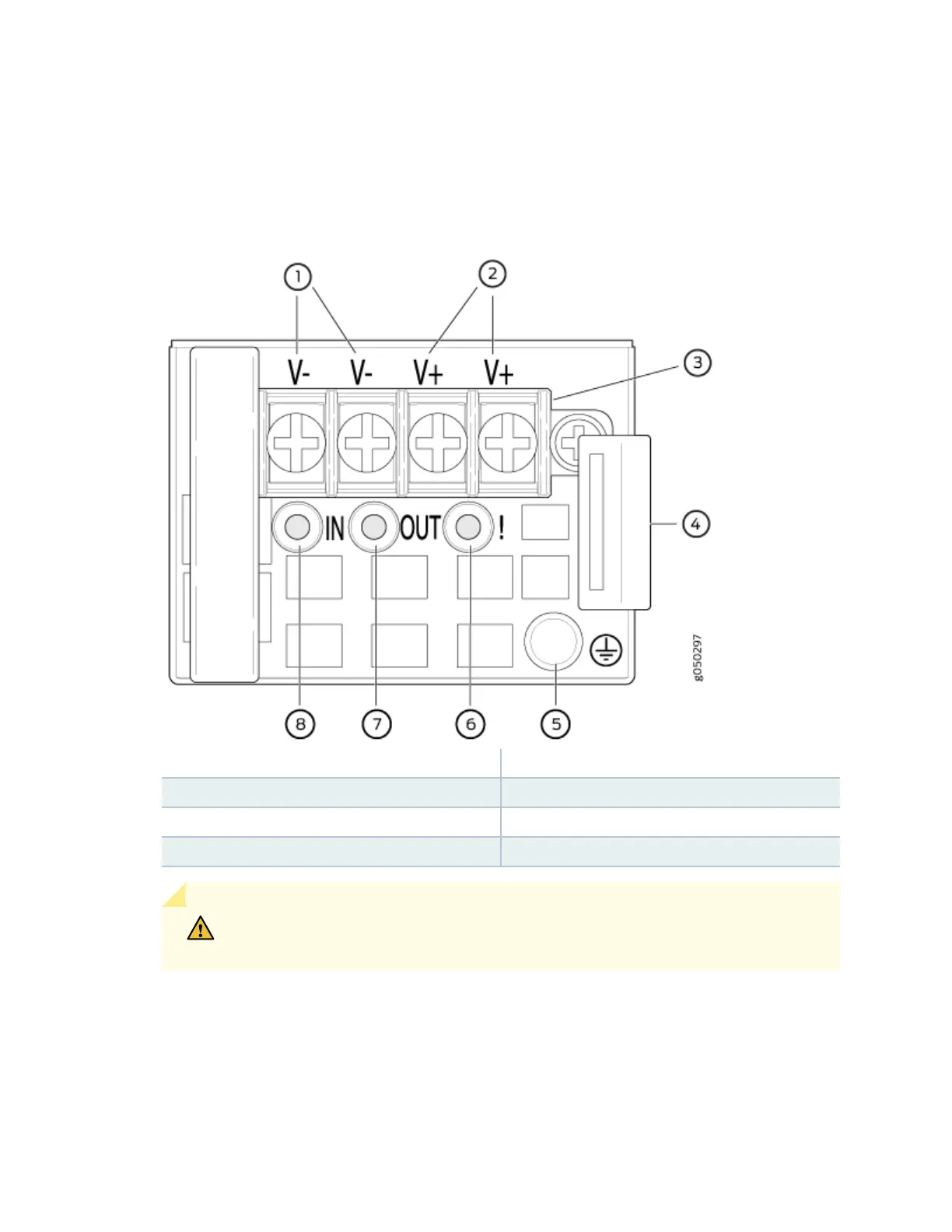
Figure 30: DC Power Supply Faceplate for an EX4600 Switch
1— Shunt negave input terminals (-48V) 5— ESD grounding point
2— Shunt posive input terminals (+RTN) 6— Fault LED
3— Terminal block 7— Output LED
4— Ejector lever 8— Input LED
CAUTION: The V+ terminals are shunted internally together, as are the V-
terminals. The same polarity terminal can be wired together from the same source
85