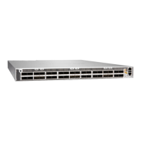
1. Move the shipping carton to a staging area as close to the installaon site as possible, but where you
have enough room to remove the system components.
2. Posion the carton so that the arrows point up.
3. Open the top aps on the shipping carton.
4. Remove the accessory kit.
5. Pull out the packing material holding the device in place.
6. Verify that the following components are in the box:
• The chassis with six fan modules and two power supplies installed
• 4-post rack mount kit—2 side mounng blades and 2 side mounng rails
NOTE: If you are installing the PTX10001-36MR on a two-post rack, you must order the
2-post rack mount kit separately.
• Sixteen athead screws for the mounng brackets (Phillips, M4 x 6 mm)
• For AC/HVDC installaons, two power cords with plugs that are appropriate for your
geographical locaon.
NOTE: Power cords are not provided for DC installaons.
• For DC installaons, four DC power cable lugs
• RJ-45 cable and RJ-45 to DB-9 serial port adapter
• RJ-45 Y-splier cable
• End User License Agreement
• Road Map card
7. Save the shipping carton and packing materials in case you need to move or ship the chassis later.
79

 Loading...