SSD status LEDs, external clock synchronizaon ports, and a USB port to support soware installaon
and recovery.
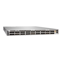
Figure 6: PTX10001-36MR Port and Management Panel
1—
ESD grounding point
6—
RJ-45 console and me of day (TOD) port
2—
12 network ports—QSFP28 cages
7—
Oine buon. Pressing and holding this
buon for more than 4 seconds turns the
device o. Pressing the buon again turns
the device back on.
3—
Clock connectors (10 MHz and 1 PPS)
8—
Reset buon (do not use unless directed by
JTAC)
4—
RJ-45 management port (10 Mbps/100
Mbps/1000 Mbps)
9—
24 network ports—QSFP56-DD cages
5—
USB port (USB 2.0 standard)
PTX10001-36MR Management Panel LEDs
IN THIS SECTION
PTX10001-36MR SSD Port LEDs | 17
PTX10001-36MR Chassis Status LEDs | 18
PTX10001-36MR Management Port LEDs | 19
The following status LEDs ae located on the management panel:
• SSD Port LEDs
16

 Loading...