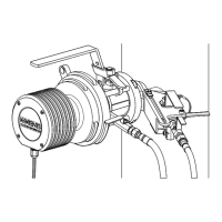
7 Regular maintenance
63
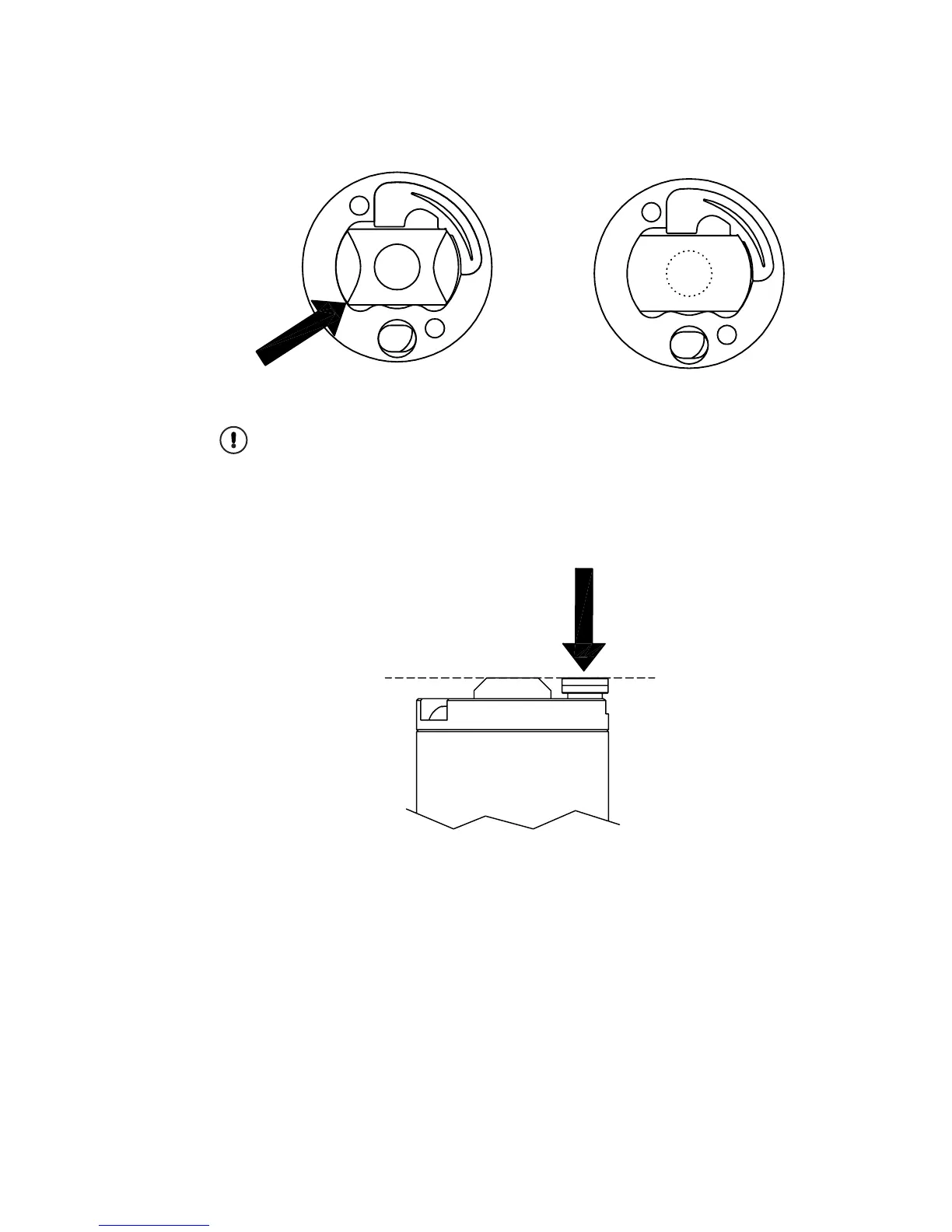
Figure 7.4 The prism and prism plate
16. Tighten the screws (c) to the bottom. Important: Make sure you are using the
original round-headed screws.
17. Check that the temperature element (a) is properly spring-loaded. In outer posi-
tion, the sensor tip should be level with the prism sensor, Figure 7.5. It should lex
inwards 2–3 mm as indicated by the arrow in Figure 7.5, but return to the outer
position.
Figure 7.5 Temperature element posion
18. Mount the core module (S), Figure 7.1. Note the alignment pin (T).
19. Mount the thermal conductor (R) with the holes aligned to the screw holes. Mount
the disc springs (P). Figure 7.1 shows which side of the springs should be up.
20. Mount the disk spring holder (N). Fasten the six screws (M) in small steps, follow-
ing the pattern of numbers in Figure 7.6. Tighten to 5 Nm torque.
 Loading...