64
PR-23 instrucon manual
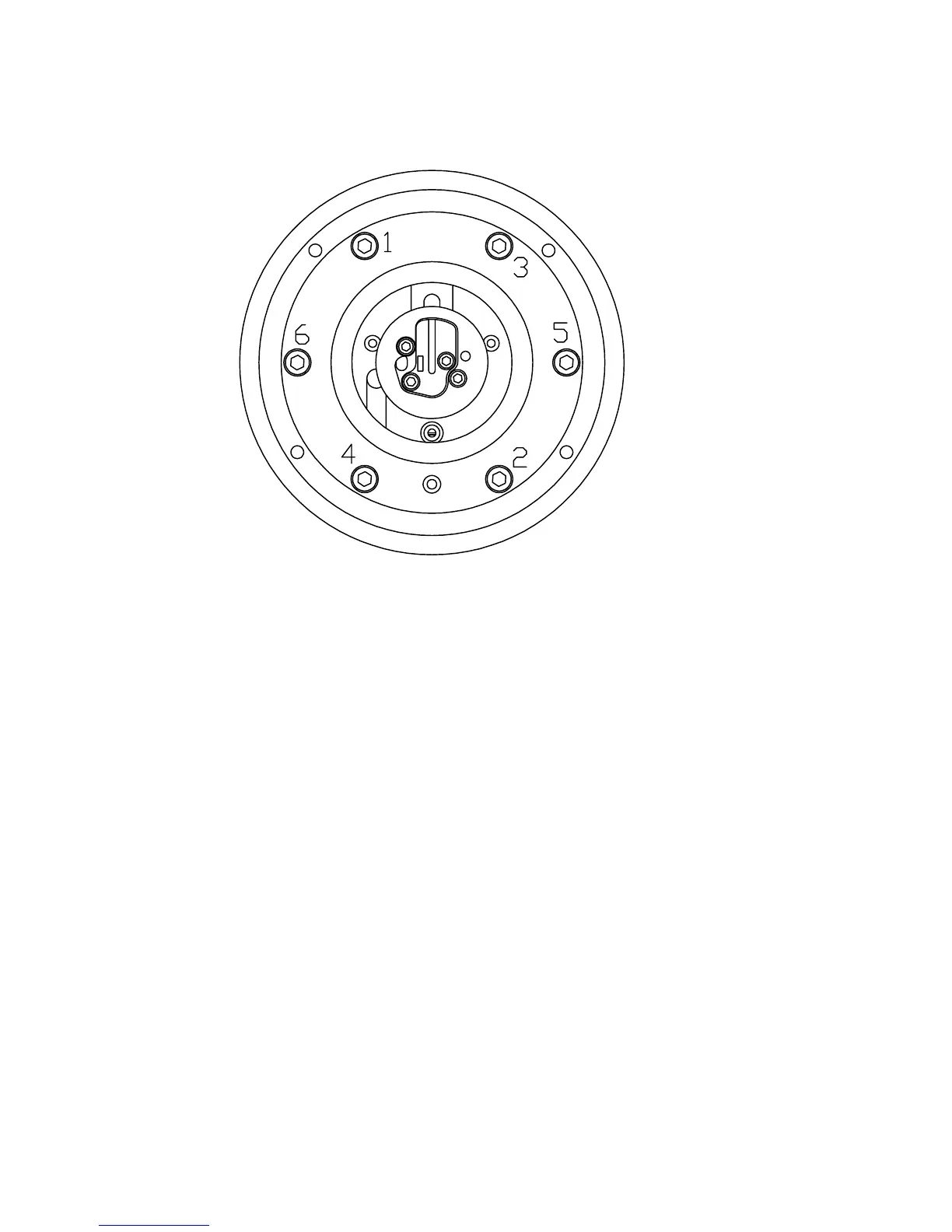
Figure 7.6 Tightening the spring holders
21. Clean the window of the CCD element. Attach the CCD card (L) to the core module
(S) by the three spacer screws.
22. Attach the sensor processor card (E) with the three hexagon socket screws. Con-
nect the ribbon cable (H), the LED connector, and the temperature element screw
terminal.
23. Replace the dryer.
24. Connect the cable from the Sensor processor card (E) to the the Bus terminator
card (F).
25. Close the sensor cover (D).
26. Place the sensor on a table with the prism upwards. Use a sharp knife to cut away
the circular piece of the gasket (d) covering the prism surface, see Figure 7.4. Sup-
port the knife on the prism surface only, as the knife may scratch the steel.
27. Perform a sensor veriication, Chapter 13.
Note: If the sensor processor card (E) was replaced, the sensor calibration para-
meters are lost. The recalibration is made using the same procedure as for sensor
veriication, Chapter 13.
28. Now the sensor is ready for process installation.
 Loading...