66 English
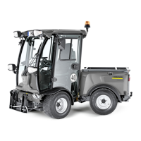
1 Travel direction selector switch
2 Indication for travel direction preselection "forwards"
3 Indication for travel direction preselection "reverse"
4 Not used
5 Double-acting hydraulic connection
AUX green
6 Double-acting hydraulic connection
Floating position for AUX red
7 Double-acting hydraulic connection
Floating position for AUX blue
8 AUX blue
Control lever
Depending on the activation of the switch for "AUX rear/at-
tachment frame with tipping mechanism", the control lever
is used for:
Controlling the rear attachments
Lifting and lowering the attachment frame with tipping
mechanism
1 Neutral position
2 Lowering and pressing down, the lever does not en-
gage
3 Lowered in floating position, the lever engages
Note
Attachment tracks the floor (e.g. brush)
4 Lifting, the lever does not engage
5 Forwards direction of travel
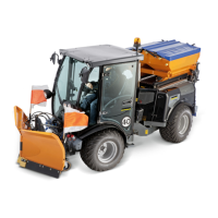
Control lever MDC variant
The control levers are used to control the front and rear at-
tachments.
1 Control lever for front linkage
2 Control lever for AUX red/blue
3 Control lever for AUX green/gray/purple
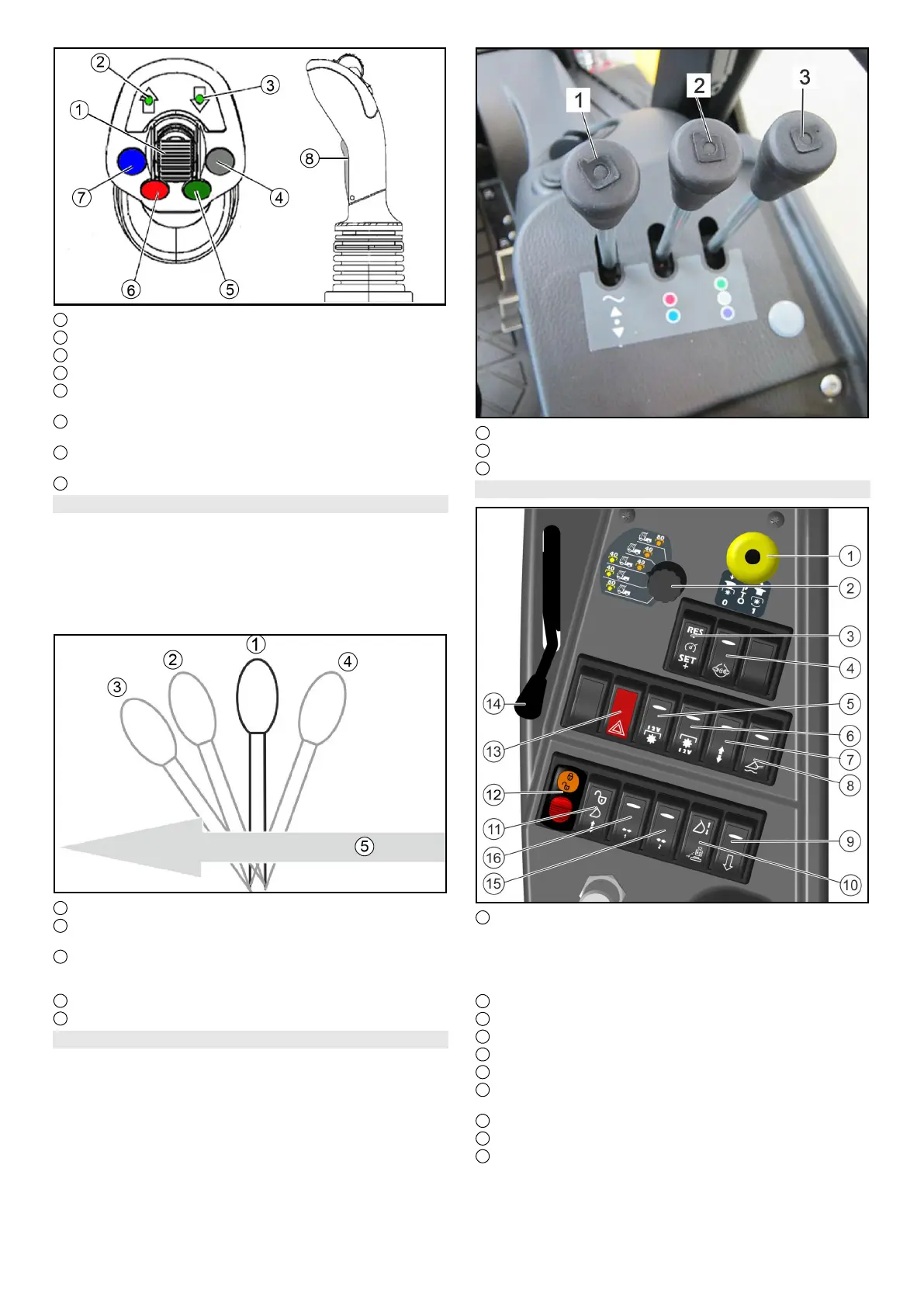
6.11.2Centre operating console for MIC 50
1 PTO on/off
Position 1: Switch on the PTO
Press the black knob and pull the button
PTO on/off
Position 0: Switch off the PTO
Press the button downwards.
2 Selector switch for hydraulic PTO
3 Tempomat
4 Differential lock
5 Electrical PTO, front
6 Electrical PTO, rear
7 Switchover for double-acting control hydraulics AUX
"rear/attachment frame with tipping function"
8 Main switch, floating position
9 Dump valve (quick-lowering for AUX rear)
10 Attachment release switch (optional)
Note
This switch is responsible both for vibration dampening
and for attachment release (both options at the same
time does not work)
 Loading...