6. Engine Removal;In
spection & Installation
6-48
10.
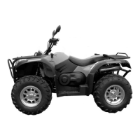
1 As shown in figure decomposition in the left
10.2 As shown in figure left cabinet remove, with
rubber hammer pump driven gear tapping oil,
the oil pump driven gear pump shaft from removed.
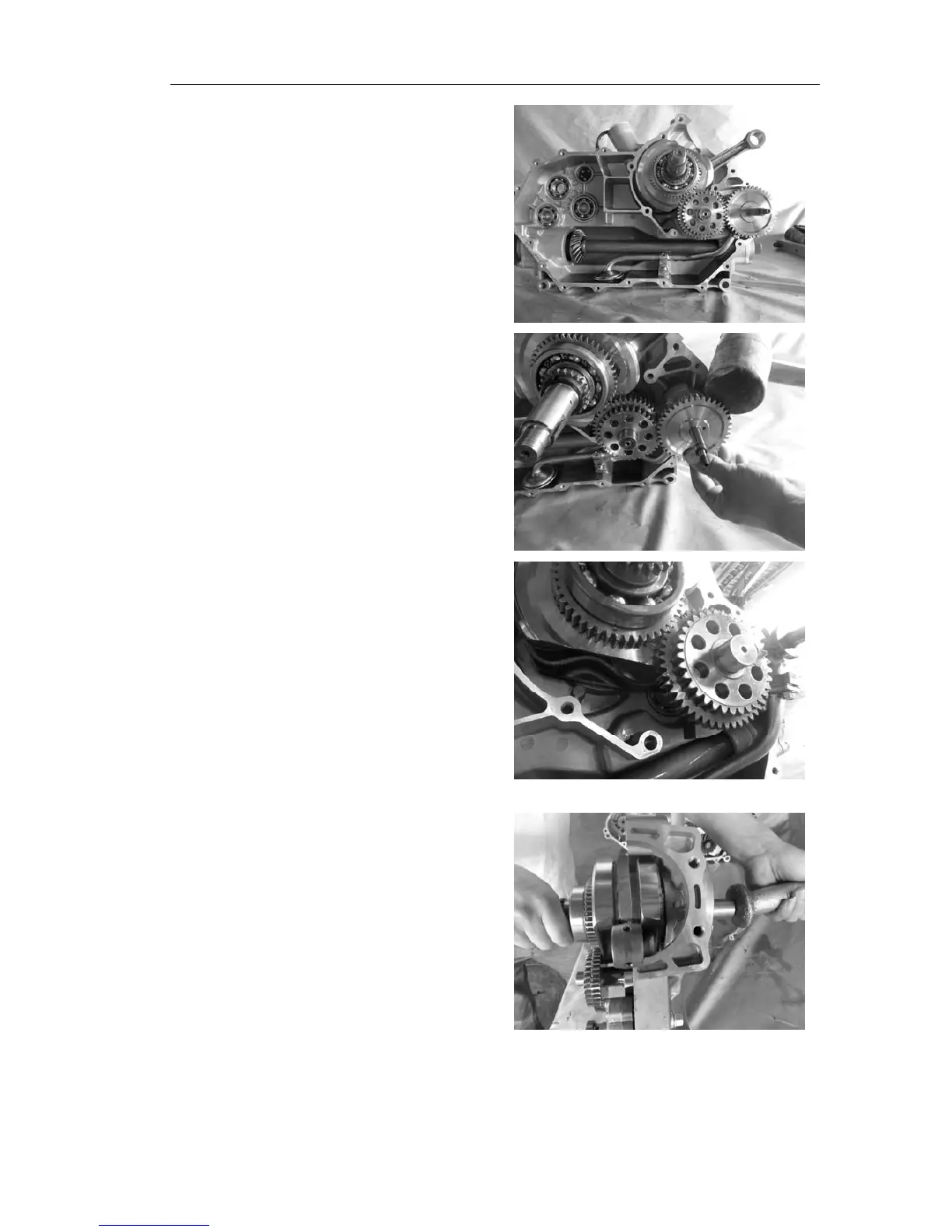
10.3 Turn will the crankshaft and balance axis,
make the crankshaft and balanced shaft jilt piece
of stagger.
10.4 Will the left upright, with tongbang striking the
crankshaft neck off balance and crankshaft axis.