6. Engine Removal;In
spection & Installation
6-61
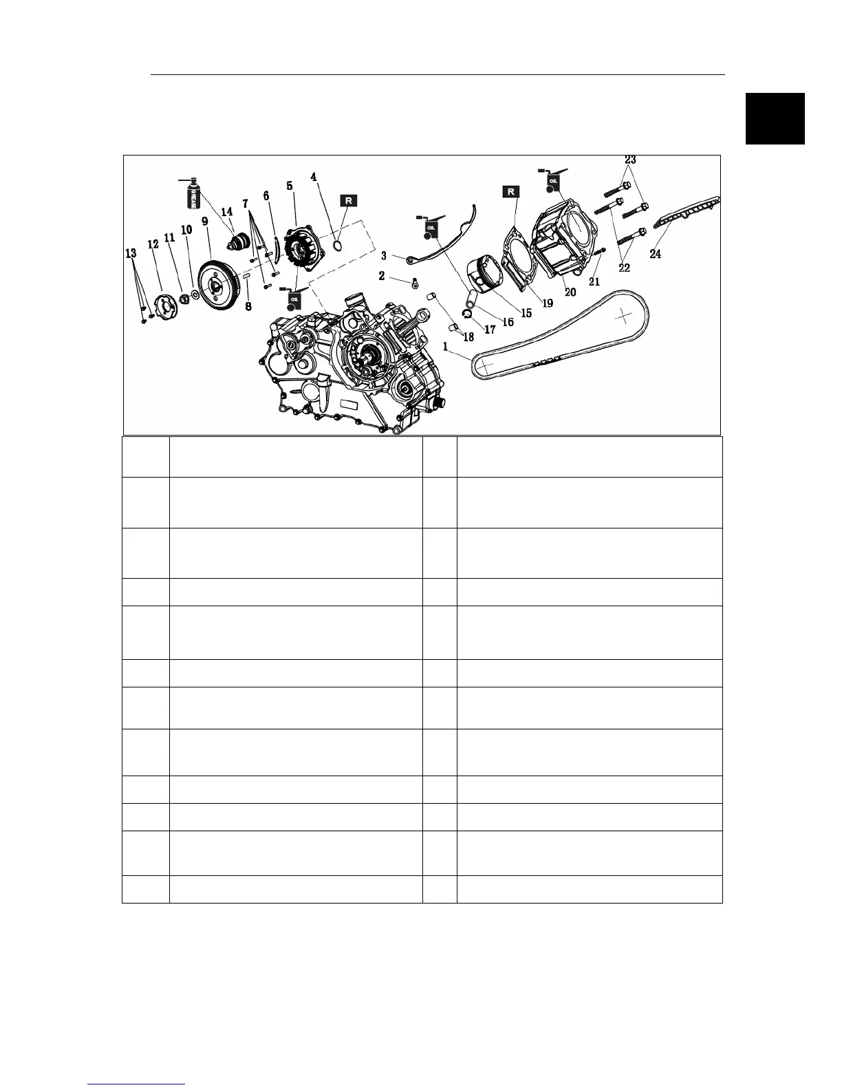
14. Cylinder
piston and flywheel assembly
.1According to the list, as shown in the assem
bly sequence
1
timing chain 13
Hexagon flange boltsM8*25
torsion75N.m
2
T
ension rod bolt
torsion10N.m
14 Beyond the clutch assembly
3
Chain tension rod 15
piston assembly
(See the piston assembly instructions)
4 O-ringΦ2.5*Φ15 16
wrist pin
5
Coil f
ixed a combination
(See a pack of coil fixed description)
17 C form block circle
6 cable
clamp 18
locating pinΦ15*12
7
Hexagon
flange boltsM6*25
torsion10N.m
19 head gasket
8 flat
key 20
Cylinder combination(See the cylinder
assembly instructions)
9 FL
YWHEEL ASSY 21
Hexagon flange boltsM6*28
11
Hex flange surface nutM16
torsion75N.m
23
Hexagon flange boltsM10*68
torsion65N.m
12
Starting joints dish 24 Chain guide a
6