6. Engine Removal;In
spection & Installation
6-52
1
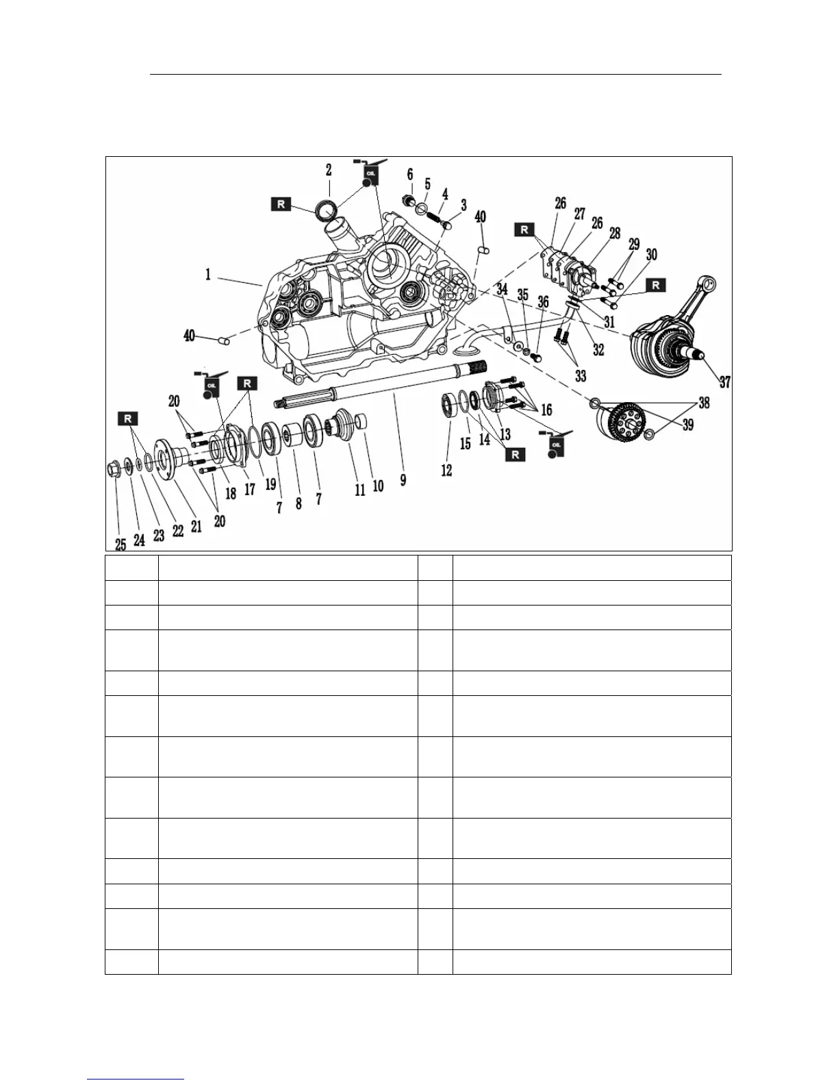
1. The left of the assembly.
1.
According to the list, as shown in the assembly sequence
1
Left the components 22 O-ringΦ2.5*Φ27
2 oil
sealΦ35*Φ48*8 23 O-ringΦ3*Φ16
3
Check valve components 24 taper washer
4 check
valve spring 25
With the lock flange surface nut M16
torsion 80N.m
5 Al
washerΦ12*Φ18*1.5 26 Points oil cover plate MATS
6
Hexagon flange bolts M12*12
torsion 30N.m
27 Points oil cover plate
7 ball-bearing
6207 28
Oil pump assembly
(See also
Oil pum
p assembly
explain)
8
Bevel gear positioning sets 29
Hexagon flange bolts M6*45
torsion 10N.m
9 output
shaft 30
Hexagon flange bolts M6*50
torsion 10N.m
10
Bevel gear positioning sets 31 filter opening
gasket
11
driven
bevel gear
32 Oil absorption plate assemblies
12 ball-bearing
6205 33
Hexagon flange bolts M6*16
torsion 10N.m
13
front bearing retainer 34 washerΦ6*Φ19*1.5