6. Engine Removal;In
spection & Installation
6-53
14 oil
sealΦ25*Φ40*7 35
spring ring 6mm
15 O-ringΦ2.5*Φ47 36
Hexagon flange bolts M6*20
torsion 10N.m
16
Hexagon flange bolts M6*22
torsio
n
10N.m
37
crankshaft assembly
17
Rear bearing cover 38 copper packingΦ20*Φ28*0.5
18 oil
sealΦ40*Φ62*8 39
Balance shaft assembly
(see b
alance
assem
bly instructions)
19 O-ringΦ2.5*Φ67 40
dowel pinΦ12*18
20
Hexagon flange bolts M8*28
torsion 25N.m
41
Oil p
ump driven gear
21
Output shaft flange constructed
1
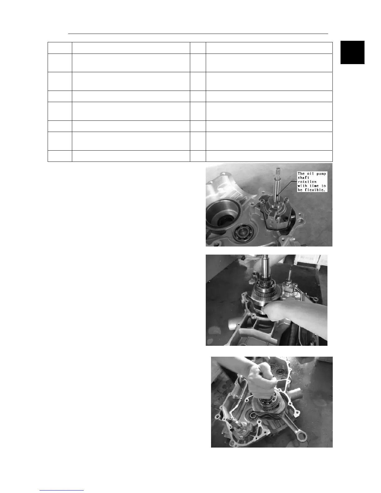
1.1 Oil pump assembly instructions
As shown in figure machine oil fixed, bolt
diagonal points to two to three times after
preloaded on tight. The oil pump shaft
rotation with time to be flexible.
11.2 As shown in figure will pack the crankshaft left
when song.
11.3 As shown in figure hand holding the
crankshaft neck to shake the crankshaft
crankshaft put in position.
6