6. Engine Removal;In
spection & Installation
6-18
2.Right cover
remove check
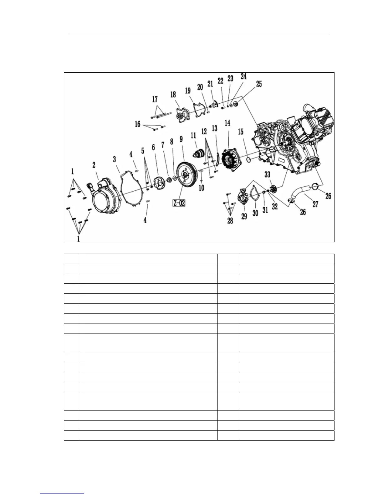
According to the list of instructions on the order
1
Hexagon flange bolts M6*30
18
Change shaft cover
2
Right box
19
Shif
t shaft cover gasket
3
Right cover gasket
20
Dowel pin Φ8*10
4
locating pinΦ6*12
21
Shif
t shaft assembly
5
Hexagon flange bolts M8*20
22
Hexagon flange bolts M6*20
6
S
tarting joints dish
23
spring washer 6mm
7
Hex flange surface nut M16
24
Wa
sher Φ6*19*1.5
8
washerΦ16*Φ32*2
25
Shif
t gears pulled move
9
The flywheel assem
bly (see Z-02 flywheel
split)
26
The pipe clip
10
flat key
27
exhalent siphon
11
Beyond the clutch assembly
28
Hexagon flange bolts M6*28
12
Hexagon flange bolts M6*25
29
water pum
p cover
13
cable clam
p
30
Pump cover gasket
14
Coil f
ixed a combination
31
Flange surface nut covered
form M7
15
O-ringΦ2.5*15
32
copper washerΦ7*Φ12*2
16
Hexagon flange bolts M6*28
33
Pum
p impeller components
17
Hexagon flange bolts M6*139