6. Engine Removal;In
spection & Installation
6-57
12.
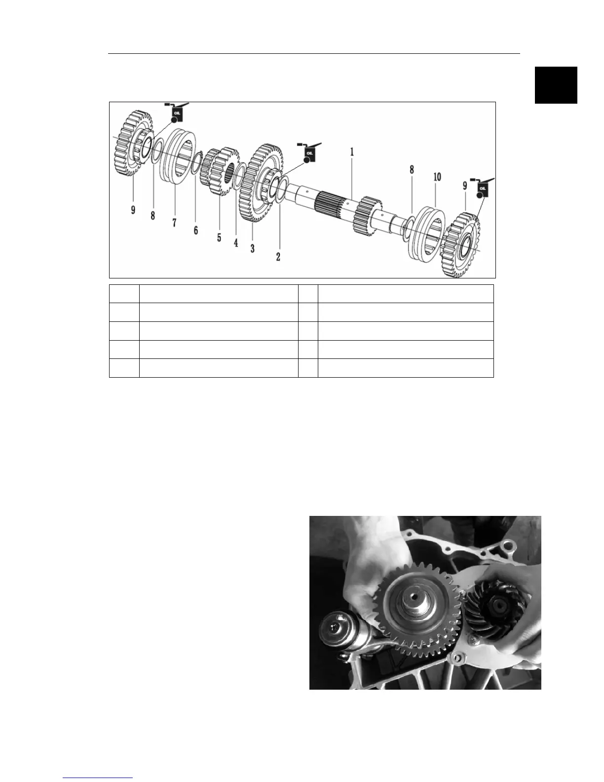
3 Deputy shaft assembly instructions
According to the list, as shown in the assem
bly sequence
1
countershaft 6 C form block circle
2 washerΦ26*Φ35*1
7 Sliding set of 1
3
Low block gear components 8 washerΦ23.5*Φ33*1
4 washerΦ26*Φ35*1.5 9
Into reverse components
5
Bridge active tooth 10 Sliding set of 2
●
"C" arch
ives circle to assembly in position .
●
W
asher assembly sequence can't be wrong, at the same time, after all gear assembly to
flexible rotation.
Z-09A
ssembly instructions
12.4Shift drum assembly, deputy shaft
combination and driven shafts combination
as shown in the cabinet together right.
2. Deputy shaft have oil way hole side down
6