6. Engine Removal;In
spection & Installation
6-54
11
.4
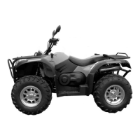
As shown in figure balance shaft markers
and crankshaft marker on is balanced shaft
after striking tongbang end, main shaft put in
place
11.5
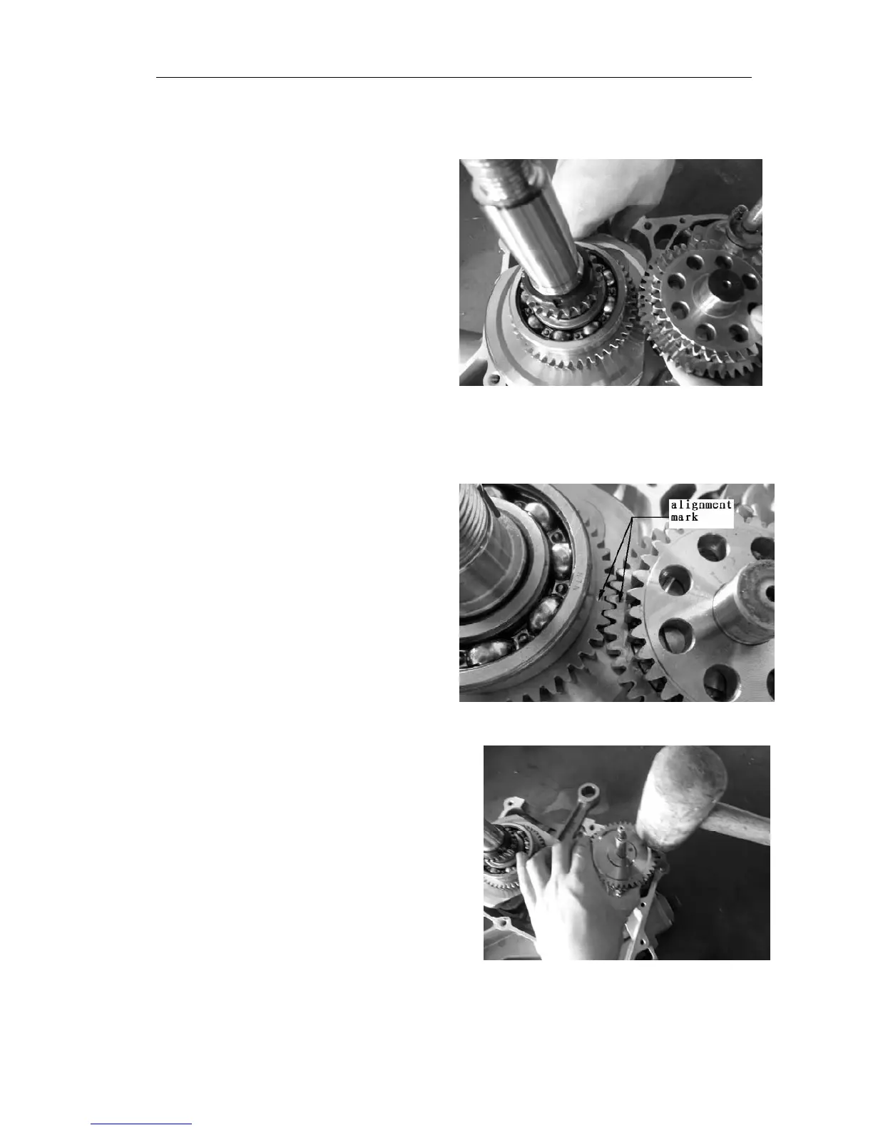
As shown in figure crankshaft balance of shaft active
teeth and balance on the driven shaft tooth marks to is.
11.6 As shown in figure oil pump driven gear
pump shaft load of are pin hole with glue stick
after tapping gear, gear from move put in place.