6. Engine Removal;In
spection & Installation
6-55
12.
The left of the assembly.
Accordi
ng to the list, as shown in the assembly sequence
12.1
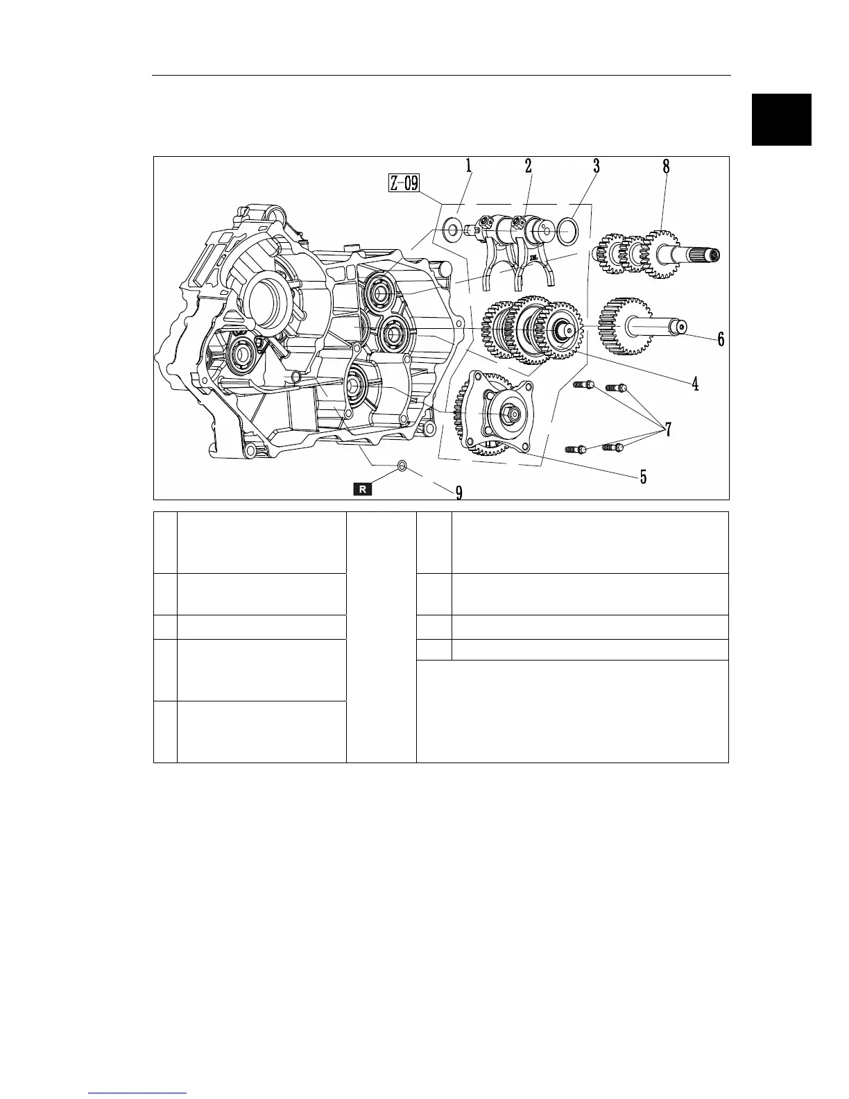
The driven shaft assembly instructions
According to the list, as shown in the assembly sequence
1 washer Φ15*Φ36*2 6
reverse gear shaft
(see the reverse shaft assembly
instructions)
2
Shift drum assembly 7
Hexagon flange bolts M8*32
torsion 30N.m
3 washer Φ32*Φ40*2 8
drive shaft
9
O-ringΦ2*Φ10
4
Deputy shaft com
bin