8. FRONT WHEEL, FRONT BRAKE,SUSPENSION,STEERING
8-6
Disasse
mbly
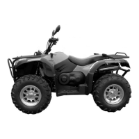
Remove:
--Footrest board(→2-6)
--Nut 1, Bolt 1
--Guard of master cylinder
Rem
ove:
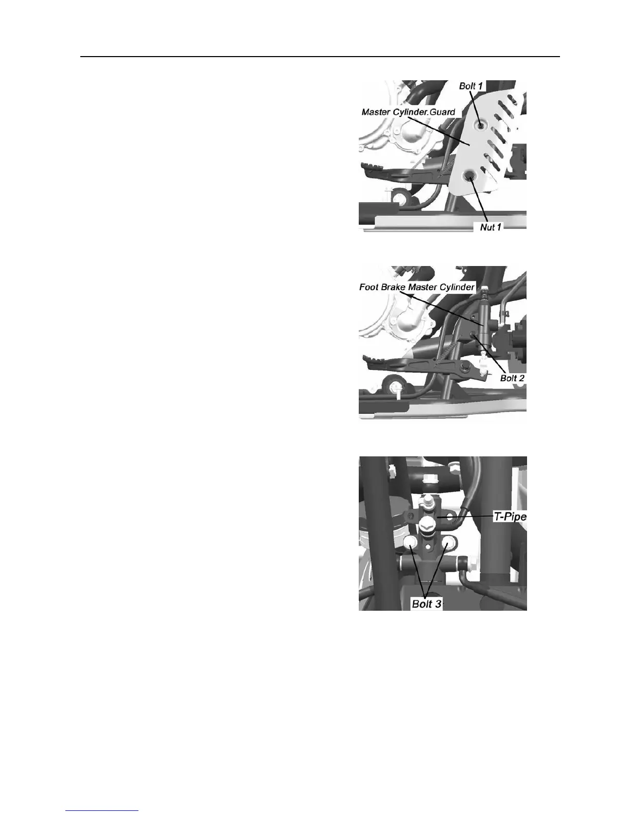
--Bolt 2
Foot brake master cylinder.
Separate foot brake master cylinder from vehicle
Asse
mbly
Reverse the removal procedure for installation.
NOT
E
Do not put the master cylinder upside down to avoid
possible entrance of air into brake system.
Keep the
master cylinder in the installation position
and fix it to the frame.
Refer to Chapter 1 for pr
oper routing of brake hose.
Check brake efficiency
after installation.
Brake Hose
T-Pipe
Rem
ove:
-- Front cover assem
bly. (→2-8)
--Bolt 3
--
Front right
absorber
--T-Pipe
Installa
tion
Reverse the removal procedure for installation
Note:
Check front and rear brake linkage after installation.