AKD2G-S Installation, Safety 1 | 6 Technical description and data
6.8.2.3 Technical data for AKD2G-Sxx-7V
Technical data for the regenerative circuit depends on the drive type and the mains voltage.
Supply voltages, capacitance, and switch-on voltages are all nominal values.
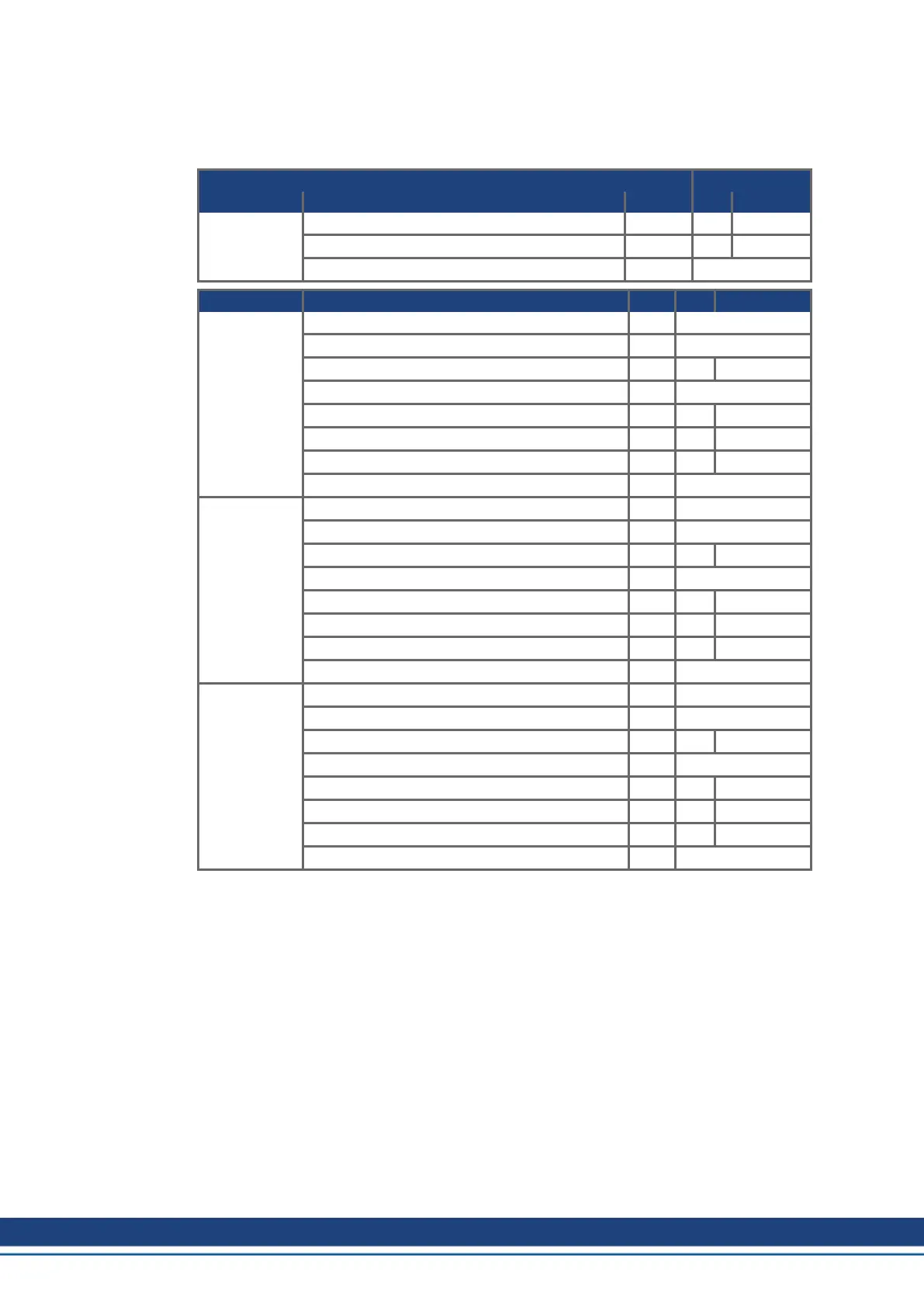
Brake circuit AC Supply
AKD2G-Sxx- Rated data Units 240V 400V/480V
7Vxxy
all types
Switch-on threshold of regenerative circuit V 380 760
Overvoltage limit V 420 840
Maximum regenerative duty cycle % 15*
AKD2G-Sxx- Rated data Units 240V 400V/480V
7V03S Internal regen resistor Ω 33
Continuous power, internal resistor W tbd
Peak brake power, internal resistor (0.5s) kW tbd tbd
External regen resistor Ω 33
Continuous brake power, external resistor kW tbd tbd
Peak brake power, external (1s) kW tbd tbd
Absorption energy in capacitors (+/- 20%) Ws tbd tbd / tbd
DC Bus Capacitance µF tbd
7V06S,
7V03D
Internal regen resistor Ω 33
Continuous power, internal resistor W tbd
Peak brake power, internal resistor (0.5s) kW tbd tbd
External regen resistor Ω 33
Continuous brake power, external resistor kW tbd tbd
Peak brake power, external resistor (1s) kW tbd tbd
Absorption energy in capacitors (+/- 20%) Ws tbd tbd / tbd
DC Bus Capacitance µF tbd
7V12S,
7V06D
Internal regen resistor Ω 33
Continuous power, internal resistor W tbd
Peak brake power, internal resistor (0.5s) kW tbd tbd
External regen resistor Ω 33
Continuous brake power, external resistor kW tbd tbd
Peak brake power, external resistor (1s) kW tbd tbd
Absorption energy in capacitors (+/- 20%) Ws tbd tbd / tbd
DC Bus Capacitance µF tbd
* depends on connected regen resistor power.
44 Kollmorgen | kdn.kollmorgen.com | Beta, December 2018

 Loading...


