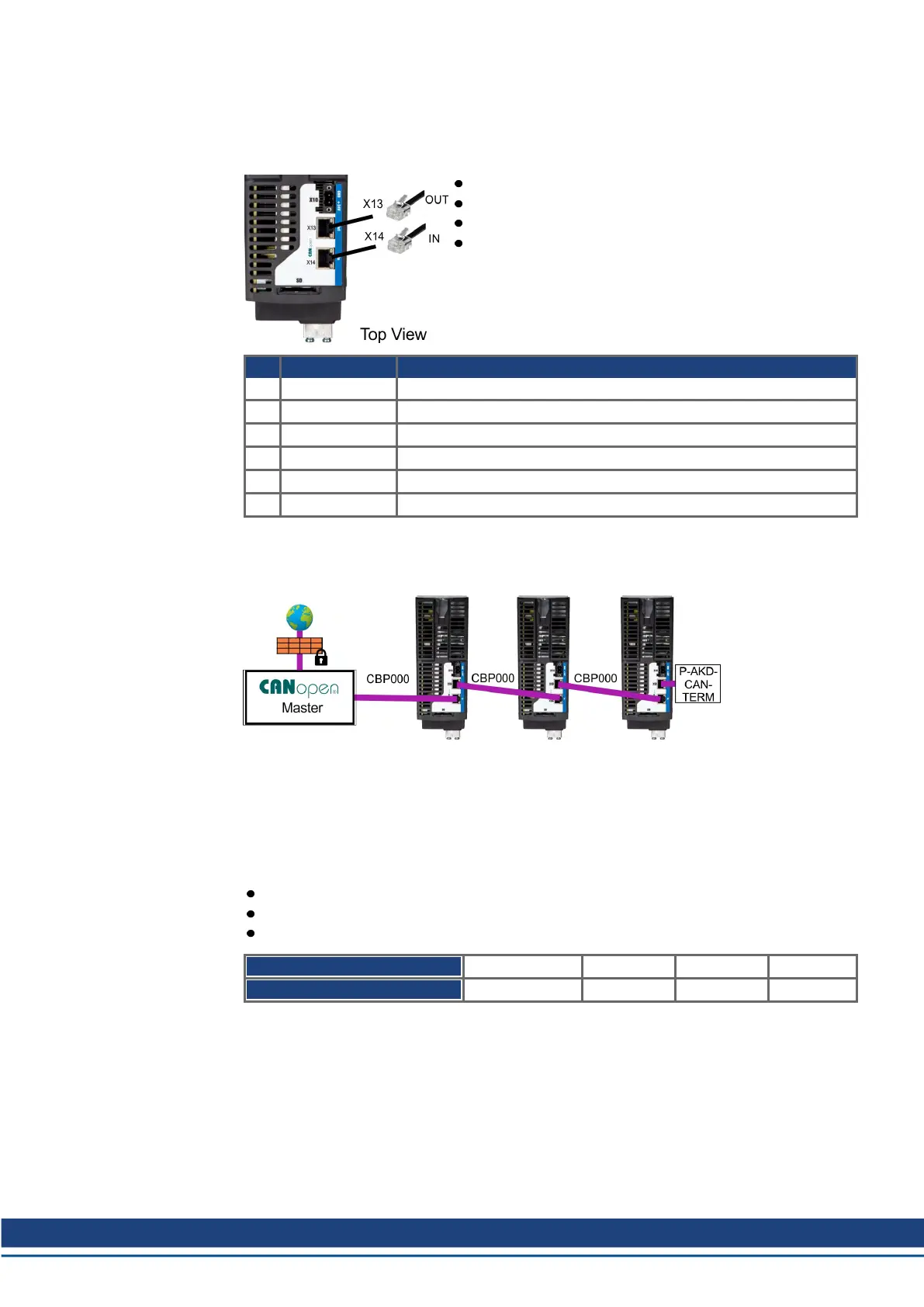
8.12 CAN-Bus Interface (X13/X14)
AKD2G drives with connectivity option CN can be connected to a CAN-Bus via two 6-pin
RJ25 connectors X13/X14.
RJ25
Up to 1000 kbit/s operation
Node ID to be set by WorkBench
Baudrate to be set by WorkBench
Pin Signal Description
1 Termination Internal Termination Resistor
2 Shield Chassis
3 CAN_high CAN bus high signal
4 CAN_low CAN bus low signal
5 CAN_GND CAN bus ground
6 Termination Internal Termination Resistor
8.12.1 CAN-Bus Topology
We recommend the use of Kollmorgen CBP000 cables.
Cable requirements
To meet ISO 11898, a bus cable with a characteristic impedance of 120 Ω should be used.
The maximum usable cable length for reliable communication decreases with increasing
transmission speed.
As a guide, you can use the following values measured by Kollmorgen; however, these val-
ues are not assured limits:
Characteristic impedance: 100–120 Ω
Cable capacitance max.: 60 nF / 1000 m
Lead loop resistance: 159.8 Ω / 1000 m
Transmission Rate (kBaud) 1000 500 250 125
Maximum Cable Length (m) 25 100 250 500
Lower cable capacitance (max. 30 nF / 1000 m) and lower lead resistance (loop resistance,
115 Ω / 1000 m) allow larger distances. The characteristic impedance 150 ± 5 Ω requires ter-
minating resistor 150 ± 5 Ω.
Communication profile
For CANopen communication profile description refer to the manual "AKD2G CAN-Bus Com-
munication".
AKD2G-S Installation, Safety 1 | 8 Electrical Installation
Kollmorgen | kdn.kollmorgen.com | Beta, December 2018 95

 Loading...


