AKD2G-S Installation, Safety 1 | 8 Electrical Installation
8.9.4 Motor Holding Brake Connection
A 24 V holding brake in the motor can be controlled directly by the drive. For proper function,
check voltage drop, measure voltage at brake input and check brake function (on and off).
Brake voltage supply via 24 V ±10% auxiliary voltage supply of the drive on X10. Minimum
and maximum brake current see Electrical Data (➜ # 36) respectively (➜ # 38).
AKD2G offers one motor brake output for every axis on connector X1 and X2 (➜ # 82).
Connector Usable for
X1 Primary motor brake axis 1
X2 Primary motor brake axis 2
No functional Safety!
Serious injury could result when the load is not properly blocked. This function does not
ensure functional safety.
Functional safety, e.g. with hanging load (vertical axes), requires an additional brake.
The Hardware Enable does not initiate a controlled stop but switches off the power stage
immediately.
Set parameter AXIS#.MOTOR.BRAKEIMM to 1 with vertical axes, to apply the brake
immediately after faults or Hardware Disable.
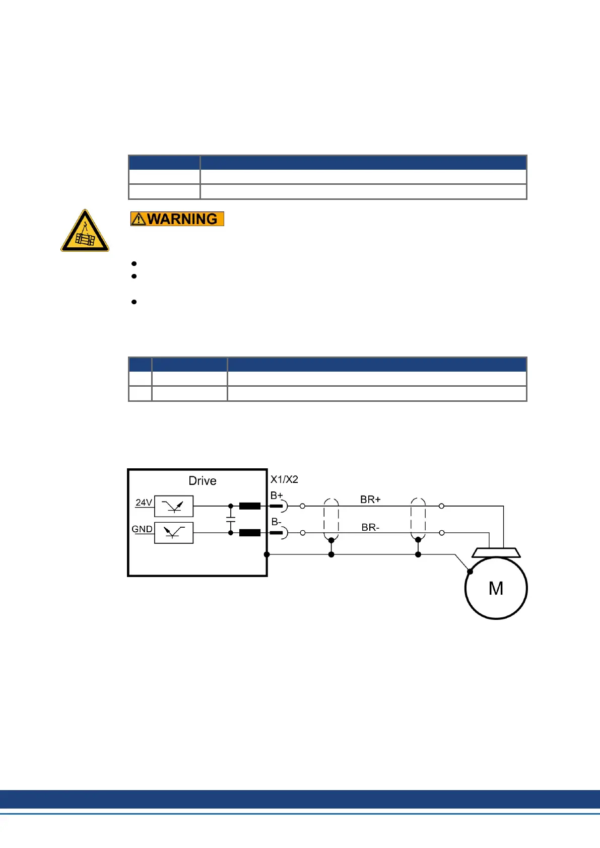
Pinout X1 / X2
Pin Signal Description
B+ BR+ Brake positive line
B- BR- Brake negative line
Wiring
Usually the brake lines are part of the Kollmorgen hybrid single cable connection to X1
respectively X2 (➜ # 78).
82 Kollmorgen | kdn.kollmorgen.com | Beta, December 2018

 Loading...


