AKD2G-S Installation, Safety 1 | 8 Electrical Installation
8.5.5 Connector pin assignments
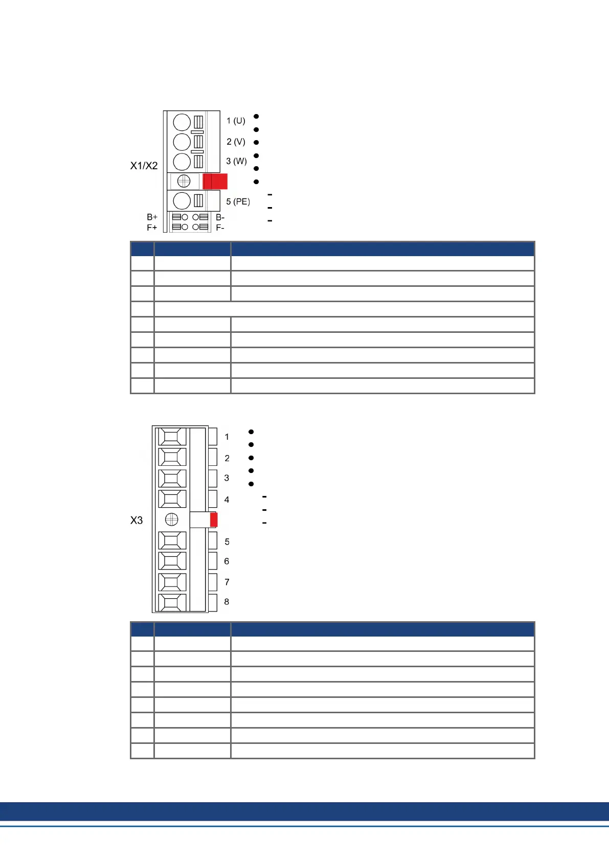
8.5.5.1 X1 and X2: Motor, Brake, Feedback 1
4 pin, pitch 7.62 mm plus 2x2 pin pitch 3.81 mm
Spring clamps
Motor power, Motor brake
X1: Input for feedback 1 (➜ # 84)
X2: Input for feedback 2 (➜ # 84)
Wiring example:
DC Bus link (➜ # 75)
Motor single cable connection (➜ # 78)
Motor dual cable connection (➜ # 80)
Pin Signal Description
1 U Motor phase U
2 V Motor phase V
3 W Motor phase W
retention latch,shield screw
5 PE Protective earth
B+ BR+ Motor holding brake +
B- BR- Motor holding brake -
F+ COM+ SFD3 + or HIPERFACE DSL +
F- COM- SFD3 - or HIPERFACE DSL -
8.5.5.2 X3: Mains, regen resistor, DC-Bus
8 pin, pitch 7.62 mm
Screw terminals
Optional T version (in process)
Mains supply, External regen resistor, DC Bus
Wiring example:
Power supply (➜ # 70)
DC Bus link (➜ # 75)
External regen resistor (➜ # 76)
Pin Signal Description
1 PE Protective earth
2 L1 3~ mains supply L1, 1~ supply L, DC supply +
3 L2 3~ mains supply L2
4 L3 3~ mains supply L3, 1~ supply N, DC supply -
5 RBint internal regen resistor
6 -RB external regen resistor -
7 +DC (+RBext) DC Bus link+ and/or external regen resistor +
8 -DC DC Bus link -
64 Kollmorgen | kdn.kollmorgen.com | Beta, December 2018

 Loading...


