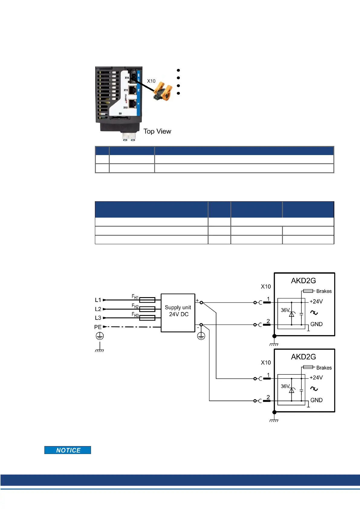
8.6.2 Auxiliary voltage power supply 24 VDC (X10)
The following diagram describes external 24 VDC power supply (PELV). The required supply
current rating depends on the use of motor brake (➜ # 35) or (➜ # 37).
2 pin, pitch 5.08 mm
Mating connector data see (➜ # 51).
Undervoltage fault limit 19 V
Overvoltage fault limit 30 V
Pin Signal Description
1 + 24 V +24 VDC supply voltage, PELV
2 GND Ground for 24 VDC supply voltage, PELV
8.6.2.1 Fusing
Use 24 VDC supply manufacturers recommendation for fusing.
24 V supply (PELV) Units Input data
single axis
Input data
dual axis
Aux. voltage supply (PELV) VDC 24 V (±10%, check voltage drop)
- control current without motor brake A 1 1.25
- control current with one motor brake A 3.5 3.75
8.6.2.2 Wiring example 24 VDC supply
Example for three phase power supply unit.
8.7 DC Bus link (X3)
Beta Drives: DC Bus sharing functionality is pending. Do not use this functionality until fur-
ther notice.
AKD2G-S Installation, Safety 1 | 8 Electrical Installation
Kollmorgen | kdn.kollmorgen.com | Beta, December 2018 75

 Loading...


