Functionality
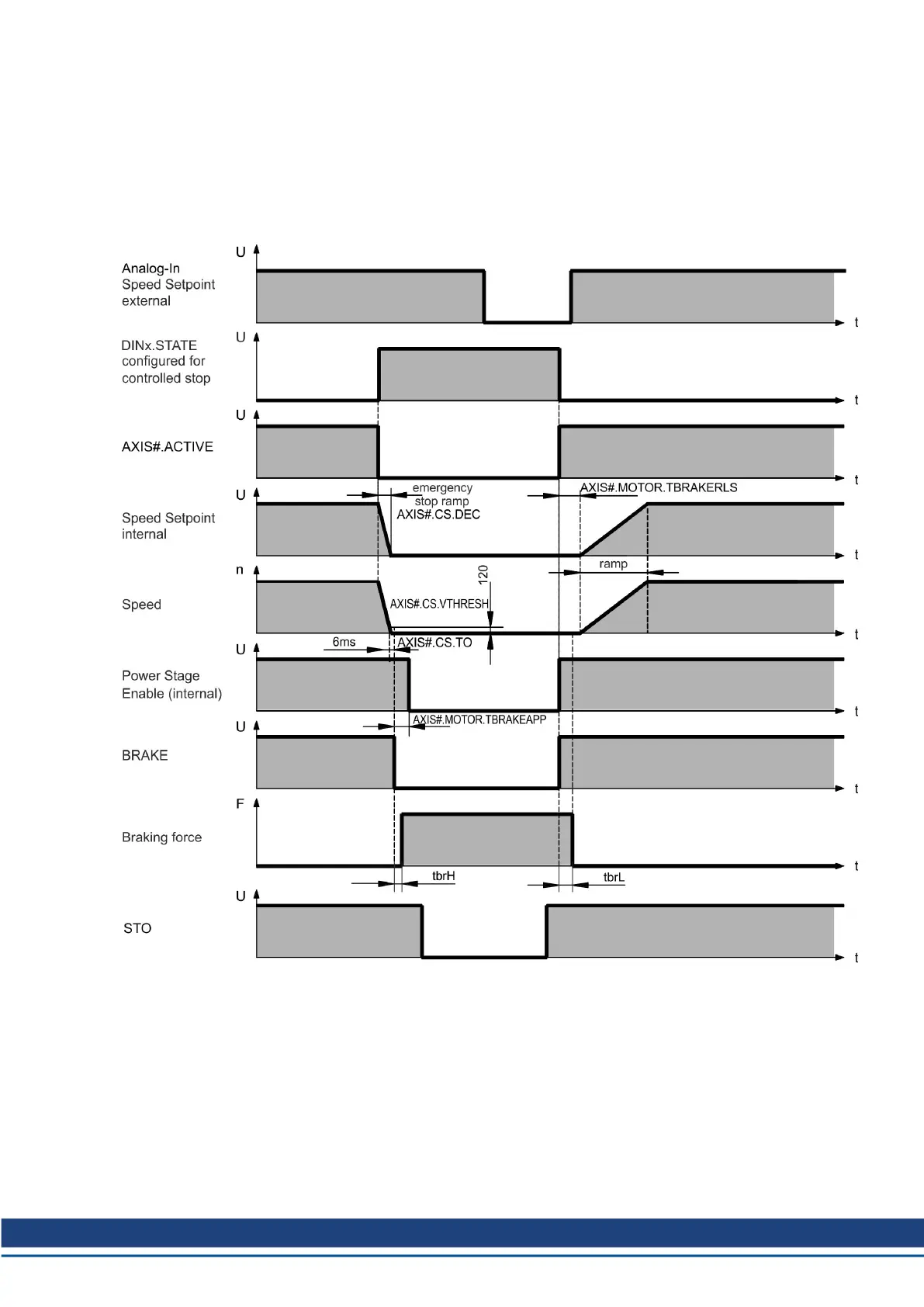
The brake function must be enabled through a parameter. The diagram below shows the tim-
ing and functional relationships between the controlled stop signal, speed,and braking force.
All values can be adjusted with parameters; values in the diagram are default values.
The drive speed setpoint is internally driven down an adjustable ramp (AXIS#.CS.DEC) to
0V.
With default values the output for the brake is switched on when the speed has reached
5rpm (AXIS#.CS.VTHRESH) for at least 6ms (AXIS#.CS.TO). The rise (t
brH
) and fall (t
brL
)
times of the holding brake that is built into the motor are different for the various types of
motor.
AKD2G-S Installation, Safety 1 | 8 Electrical Installation
Kollmorgen | kdn.kollmorgen.com | Beta, December 2018 83

 Loading...


