9.3.5.3 External encoder S1-2
Incremental encoder (TTL) or encoder with SSI signals can be connected to X31. Supply
voltage for the external encoder must be connectoed to X30/11 (+) and X30/22 (-).
X31 Pin Incremental encoder SSI Encoder
1 Channel A+ Clock +
2 Channel B+ Data +
3 Reference Z+ n.c.
4 Supply U+ Supply U+
5 Shield n.c.
6 Channel A- Clock-
7 Channel B- Data-
8 Reference Z- n.c.
9 Supply 0 V Supply 0 V
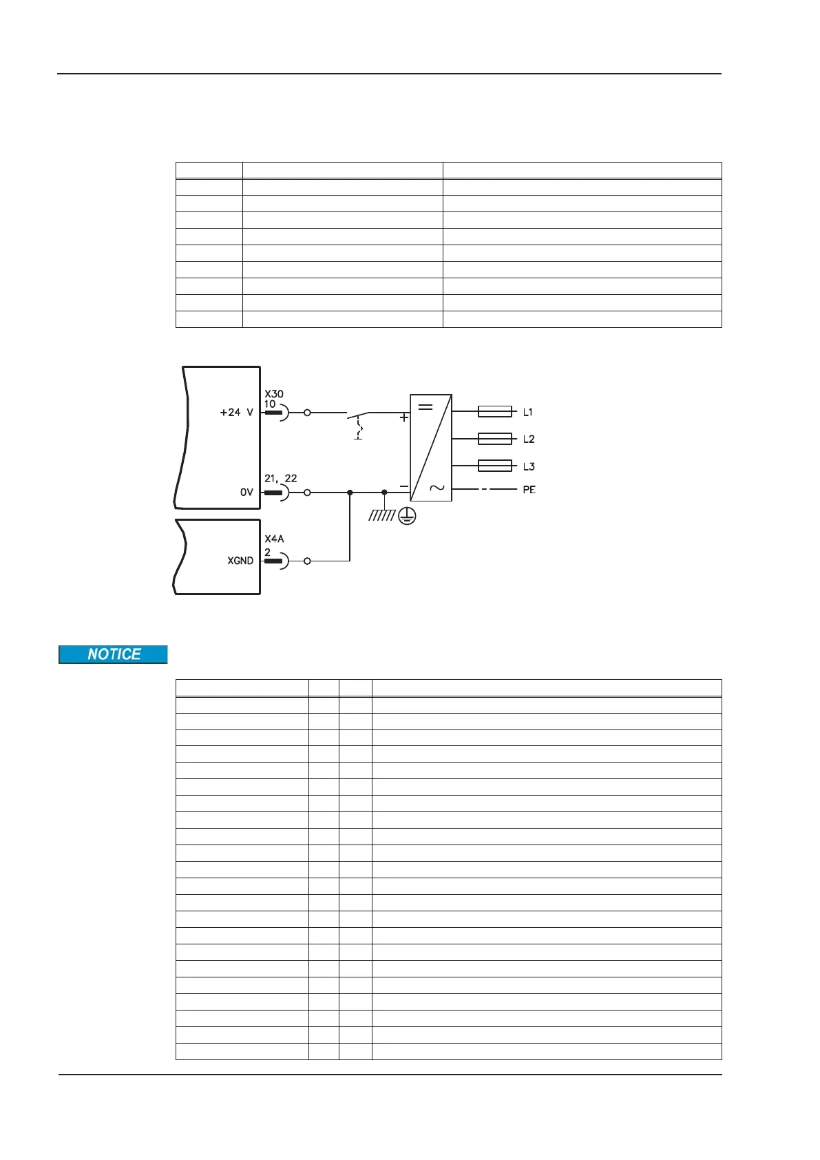
9.3.5.4 Wiring supply voltage 24 V for digital outputs
Input STO1-Enable [X4B/6]
must not be connected.
9.3.5.5 Safe inputs and outputs S1-2
Inputs X30/1 SS1_Activate and X30/20 SS1_SIL3/Reset must always be connected.
Only tested outputs from a safety control system may be connected to all inputs on X30.
X30 Pin E/A Description
SS1 Activate 1 I Activates function SS1
I0 2 I Programmable, activate safety function X
I1 3 I Programmable, activate safety function X
I2 4 I Programmable, activate safety function X
STO Acknowledge 5 O Status: STO activated
O0 6 O Programmable, status: safety function X activated
O1 7 O Programmable, status: safety function X activated
O2 8 O Programmable, status: safety function X activated
O3 9 O Programmable, status: safety function X activated
24V Supply 10 - 24V supply of digital outputs
Encoder Supply 11 - Power supply for external encoder
I3 12 I Programmable, activate safety function X
I4 13 I Programmable, activate safety function X
I5 14 I Programmable, activate safety function X
I6 15 I Programmable, activate safety function X
Ready 16 O Message "Safety card is ready to operate"
SBC+ 17 O Control external brake +
SBC- 18 O Control external brake -
STO SIL CL3 19 O Output single
SS1 SIL CL3/Reset 20 I Input for SIL CL3 and Reset
0V Supply 21 - 0V supply of digital outputs
0V Supply 22 - 0V supply of digital outputs
156 S701x2-S724x2 Instructions Manual
Expansions 07/2014 Kollmorgen

 Loading...


