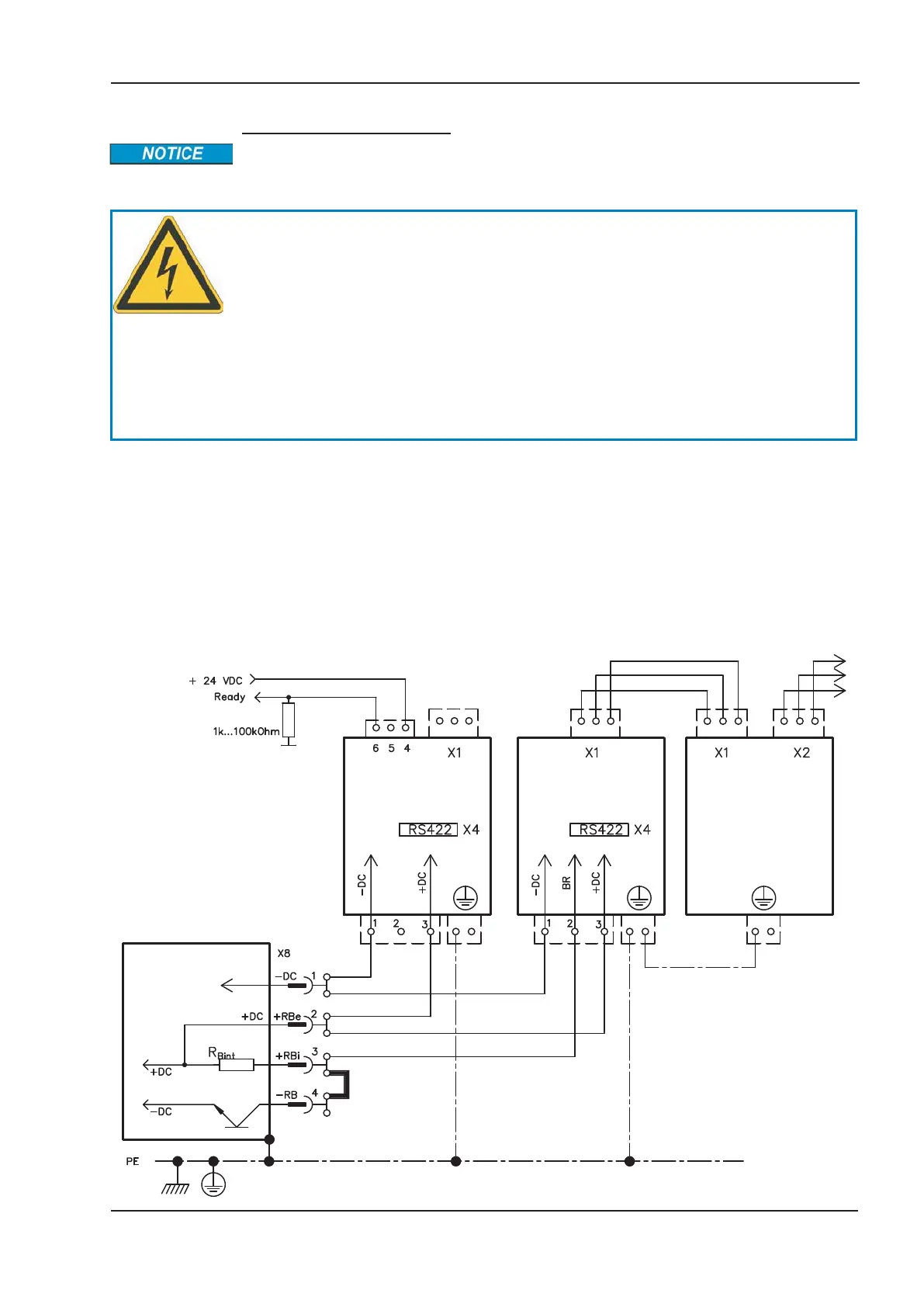
Wiring example KCM Modules
Maximum cable length between servo amplifier and S700 module: 500 mm.
Twist the cables +DC/-DC. Longer cable lengths require shielding. Ensure that the
polarity is correct; swapping round DC+/DC- will destroy the KCM modules.
DANGER
DC Bus link terminals in servo systems carry high DC voltage of up to
900 V. Touching the terminals while they are carrying voltage is extremely
dangerous. Switch off (disconnect) the line voltage. You must only work
on the connections when the system is disconnected.
It can take over an hour for the modules to self-discharge. Check the
state of charge with a measuring device that is suitable for a DC voltage
of up to 1,000 V. When measuring a voltage of over 60 V between the
DC+/DC- terminals or to ground, wait some minutes and measure again
or discharge the modules as described in the KCM instructions manual.
KCM-S: Connect the BR connection to the S700 with the most frequent regenerative bra-
king processes in the system. This S700 must have an active internal or external brake
resistor. For setup, enable the S700 and operate the driving profile that causes the brake
chopper to respond. The KCM-S determines the chopper threshold and begins to charge;
LED flashes. The energy stored is available the next time acceleration happens.
KCM-P: The KCM-P begins the charging process at approx. 470 V DC; the LED flashes.
If the power supply fails, the module provides the servo amplifier with the stored energy
that is required to bring the drive to a standstill in a controlled manner (this only applies to
the power supply voltage; battery-back the 24 V supply separately).
S701x2-S724x2 Instructions Manual 73
Kollmorgen 07/2014 Electrical installation
KCM-P KCM-E
KCM-S
S700

 Loading...


