2-136 Service Manual
7526
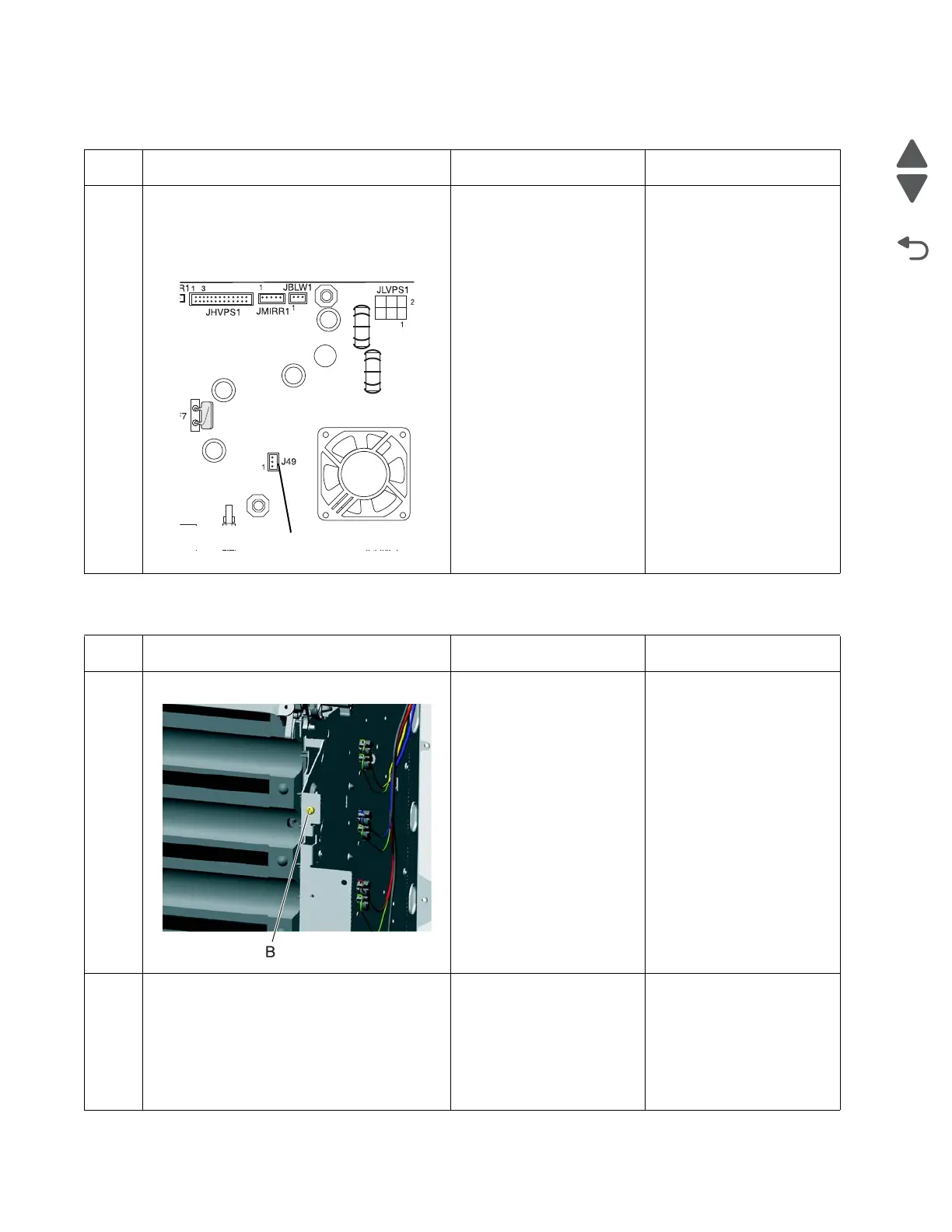
956.xx—System board failure service check
5 V interlock switch service check
Step Questions / actions Yes No
1 1. Turn the printer off.
2. Remove the rear frame cover. See “Rear
frame cover removal” on page 4-37.
3. Check the cable in connector J49 (A) for
proper connection to the system board.
Is the cable seated correctly?
Replace the system board.
See “System board
removal” on page 4-157.
Reseat the cable.
Step Questions / actions Yes No
1 Is the +5 V switch (B) damaged? Replace the 5 V interlock
switch. See “5 V interlock
switch cable removal” on
page 4-48.
Go to step 2.
2
1. Turn the printer off.
2. Remove the rear frame cover. See “Rear
frame cover removal” on page 4-37.
3. Check the cable in connector JINT1 for
proper connection to the system board, for
pinch points, and for any other damage to
the cable or connector.
Is the cable damaged?
Replace the 5 V interlock
switch. See “5 V interlock
switch cable removal” on
page 4-48.
Go to step 3.