CHAPTER 4: ELECTRICS 4 - 3
TRYTON 112 CNC
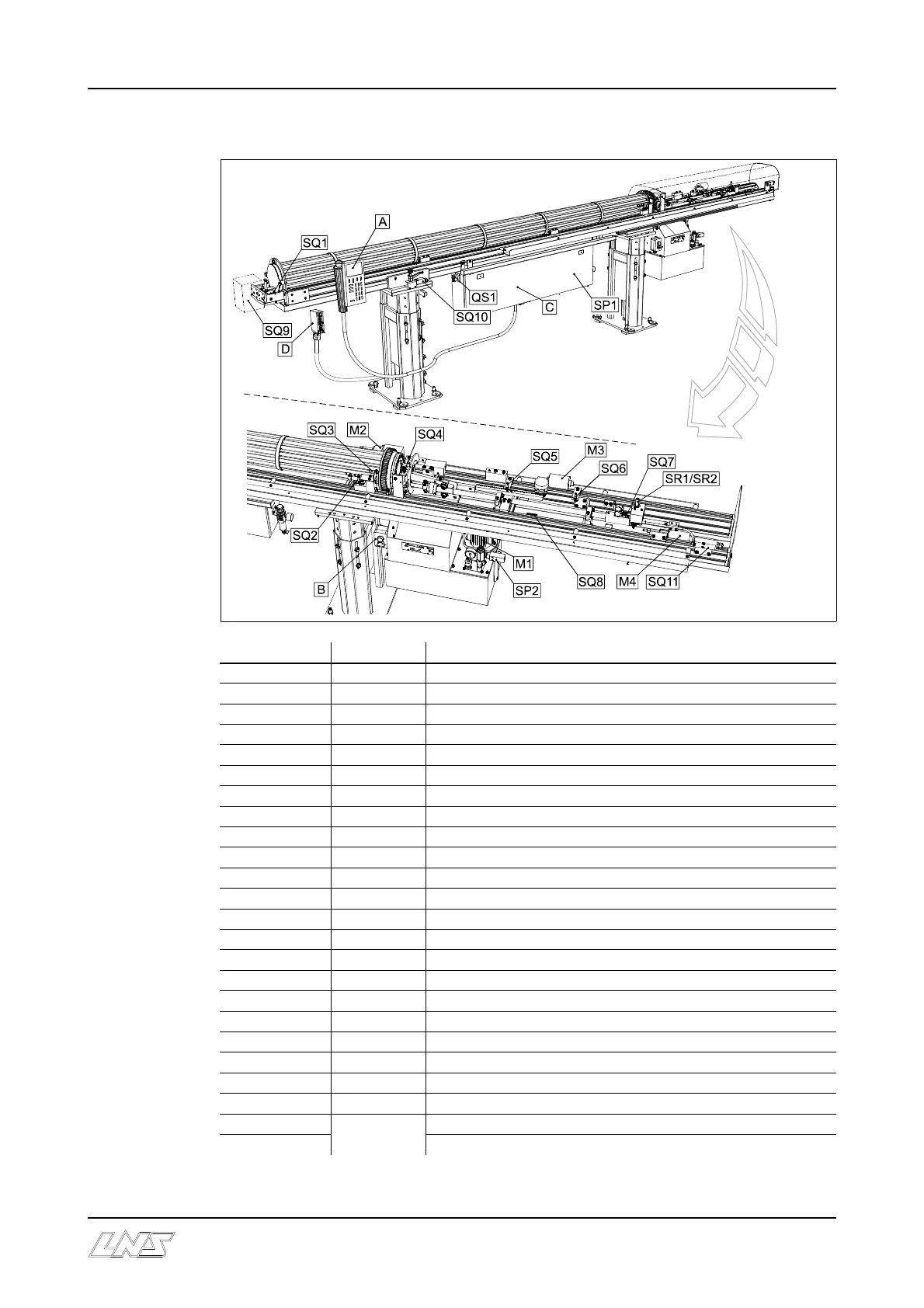
1.2 Layout of electrical elements on the bar feed system
Designation Ordering Nr Description
A 4.551 Remote control station
B (*) Stationary control
C (*) Control cabinet
D 4.068/4.074 24 pin connector with cover (depending on interface)
M 1 3.189 Hydraulic pump motor
M 2 4.643 Barrel-indexing motor
M 3 4.396 Connector motor
M 4 4.348 Cable motor
QS 1 4.242 Main disconnect switch
SQ1 4.391 Positioning stopper proximity switch
SQ2 4.391 Barrel indexing
SQ3 4.391 Indexing hole detector (Hybrid)
SQ4 4.391 Material proximity detector
SQ5 4.391 Detector: Front connector
SQ6 4.391 Detector: Rear connector
SQ7 4.391 Detector: Locked piston
SQ8 4.620 Magnetic bar-end detector
SQ9 Pneumatic outboard support detector (optional)
SQ10 4.484 Loading arm security switch (option)
SQ11 4.291 Main access cover safety switch
SP1 (*) Pneumatic pressure switch
SP2 (*) Hydraulic pressure switch
SR1
4.619
Pulse generator: Counting direction
SR2 Pulse generator: Counting
(*) See following page