LX8000 version 0.96 April 2008
Page 68 of 85
Please check, if both units are connected correctly, before first power on. The power wires
(red and blue) should be connected to the main LX8000 digital unit.
Even there is an automatic fuse in the instrument it is VERY IMPORTANT to use an
external fuse (max. 3A). Power supply cables should use a minimum of 0.5mm²
wires. To prevent damage to LX8000 digital unit after a short circuit on the
485bus there is an automatic fuse.
If a short circuit happens then the 57 mm unit will not work any more, but the reason is not
the defect of 57mm unit, but hot automatic fuse. Turn off the LX8000 system and wait for
the automatic fuse to cool down.
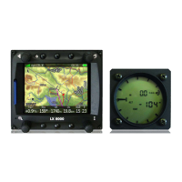
8.1 Mounting LX8000
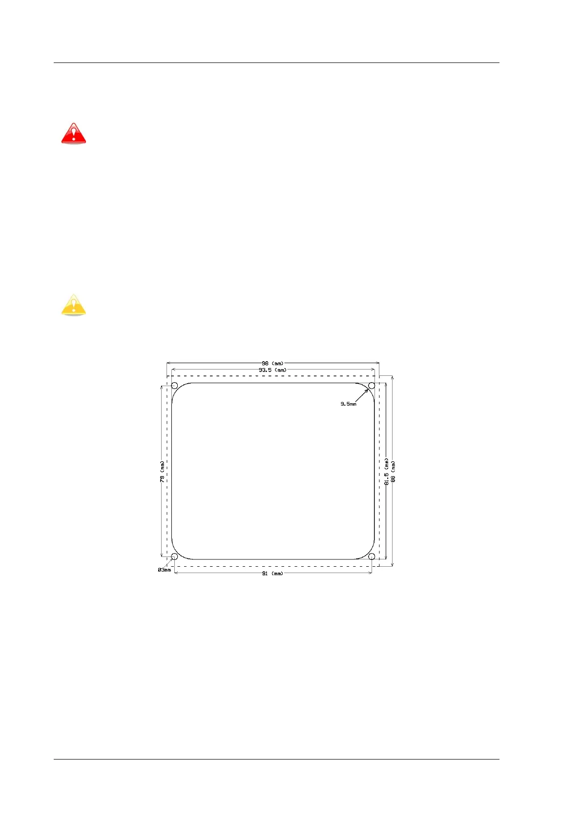
Prepare the cut-out in the instrument panel according to the drilling template.
Position the LX8000 digital unit in the cut-out in the instrument panel. Tighten the LX8000
digital unit with the 2,5mm screws.
To mount LX8000 is not necessary to remove rotary knobs.
Mounting template is shown on picture below (not in scale!):
LX8000 vario unit should be mounted to standard 57 mm hole.
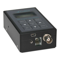
8.2 Installation of options
All options (LX8000D, Remote Control, Voice Module, Compass Module, secondary vario
indicators) are prepared to be connected to RS485 system bus by use of 485 splitting units.
Installation of any option is plug and play and therefore requires only mechanical installation
works. LX8000 digital unit also powers all the bus connected devices. An automatic fuse built
into the LX8000 digital unit prevents damage to the digital unit should a short circuit in
wiring or in some attached device will occur.