Driving modes
6.6 Installing/removing the supporting box
Operating Manual GMK6300L 3 112 xxx en 6 - 87
xx.xx.xxxx
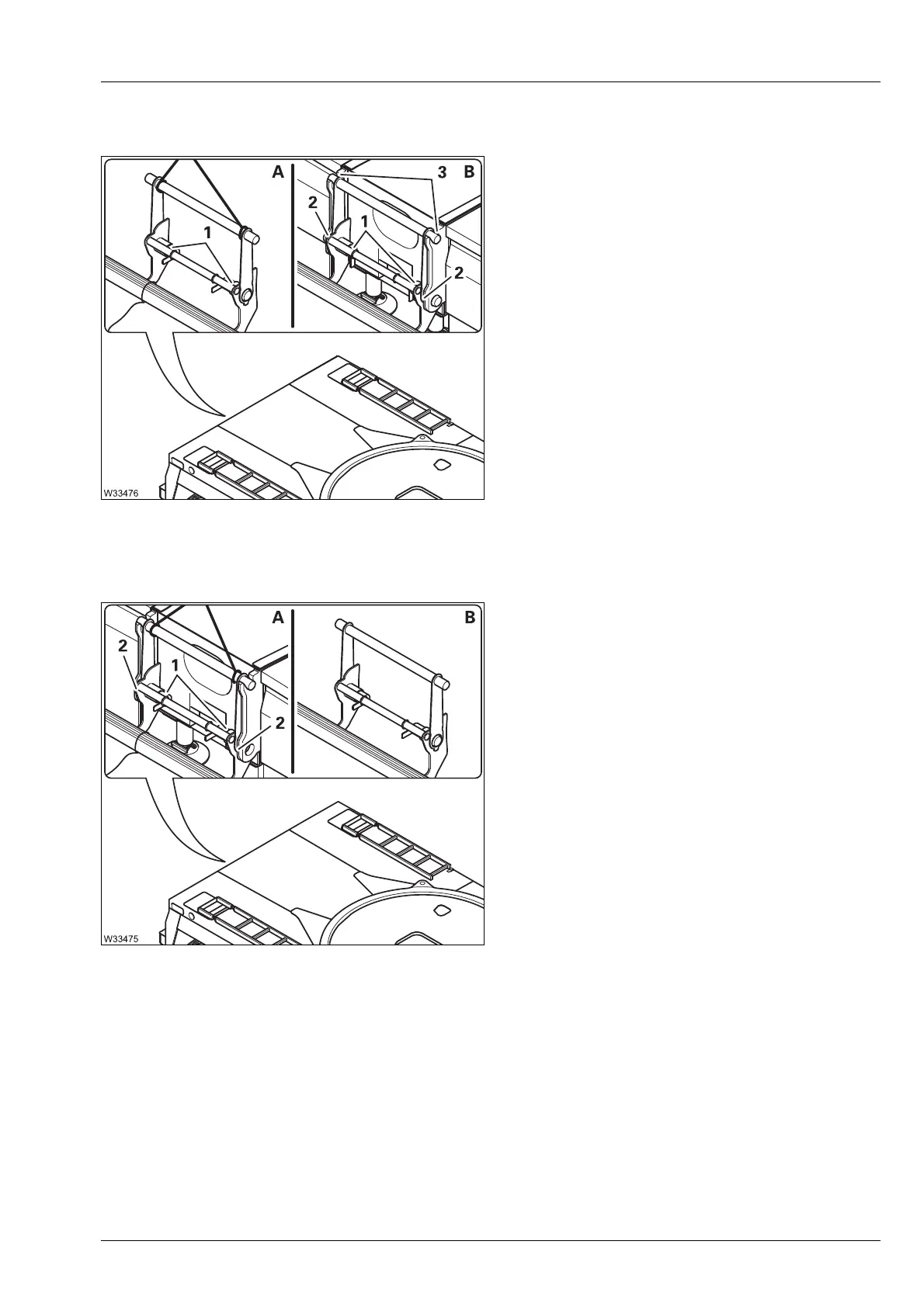
Installing Therear bumper is within one of the radii permitted by the RCL.
• (A) – Sling the rear bumper.
• (B) – Lift the rear bumper vertically over the
bracket (3).
• Hang and align the rear bumber in the brack-
ets (3) until the connecting points (2) line up.
• Release the pins (1) insert them into the
connecting points (2).
• Secure the pins – lever vertical.
• Remove the lifting gear.
Removing
• Raise the main boom until you are able lift the rear bumper vertically
upwards.
• (A) – Sling the rear bumper.
• Remove the pins (1) from the connecting
points (2) and secure them – lever horizontal.
• (B) – Lift the rear bumper vertically off the
carrier.
• Remove the lifting gear.
 Loading...


