OM-267357 Page 32
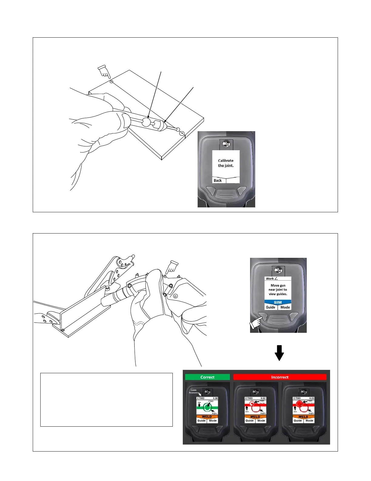
3. Calibrate both ends of weld joint. System chimes and touchscreen displays checkmark to indicate successful calibration. See Section 6-4 and
Figure 7-13.
Calibrate at both
ends of weld joint.
Avoid tack points.
161-047
Clamp weld coupons before
calibrating.
(Weld clamps
are not shown.)
See Section 4-1 for joint cali-
bration tool storage location.
1 Joint Calibration Tool
2 Joint Calibration Tool
Marker
The joint calibration tool has
three markers. Hold tool at slight
angle as shown so markers are
visible to cameras. Be sure
hands do not block markers.
For single-bevel groove welds,
the joint calibration tool must be
angled toward the square
(non-beveled) part. The
workpiece may have to be rotat-
ed to accommodate.
For single-V welds, if the target
work angle is not 0, the joint cali-
bration tool must be angled to-
ward the pass. The workpiece
may have to be rotated to ac-
commodate.
1
2
Corresponding
SmartGun Display
Figure 7-13. Calibrating Weld Joint
4. Close cover and move gun near weld joint to view real-time, pretest, and gun positioning guides (Figure 7-14).
161-049 / 049
Do not cover
SmartGun
LEDs.
Corresponding
SmartGun Display
SmartGun Information
Press and hold Mode button to switch between modes.
WELD Mode Arc-On weld tests
SIM Mode Arc-Off simulation tests
Visual guides indicate proper gun positioning prior to tests.
Move gun near the weld joint to view now.
Use Guide button to select parameter for vibration feedback.
Figure 7-14. Using SmartGun Position Guides