Cleaning and Disinfection Maintenance
7 - 14 046-004667-00 A7™ Operating Instructions
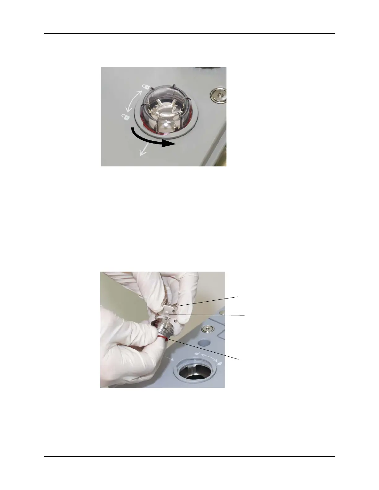
1. Remove the valve dome (see FIGURE 7-11), turning it counterclockwise.
FIGURE 7-11 Valve Dome Removal
CAUTION: The valve disc in each of the inhalation and exhalation valve assemblies
on the breathing system is fragile and must be handled with care while
removing the valve cage from the valve assembly.
2. Remove the valve cage (see FIGURE 7-12). The six prongs of the valve cage have tabs that
secure cage onto the valve assembly. While noting the previous CAUTION, use two hands to
remove the valve cage by gently manipulating the prongs to release the tabs. As the valve
cage is lifted away from the assembly, ensure that the valve disc does not fall out.
3. Remove the valve disc from the valve cage (see FIGURE 7-12).
4. Remove the O-ring from the bottom of the valve assembly (see FIGURE 7-12).
FIGURE 7-12 Valve Cage Removal
CAUTION: The valve disc in each of the inhalation and exhalation valve assemblies
on the breathing system is fragile and must be handled with care while
removing the valve cage from the valve assembly.
Valve Cage
Valve Disc
O-ring