A7™ Operating Instructions 046-004667-00 1 - 17
Product Description Physical Views
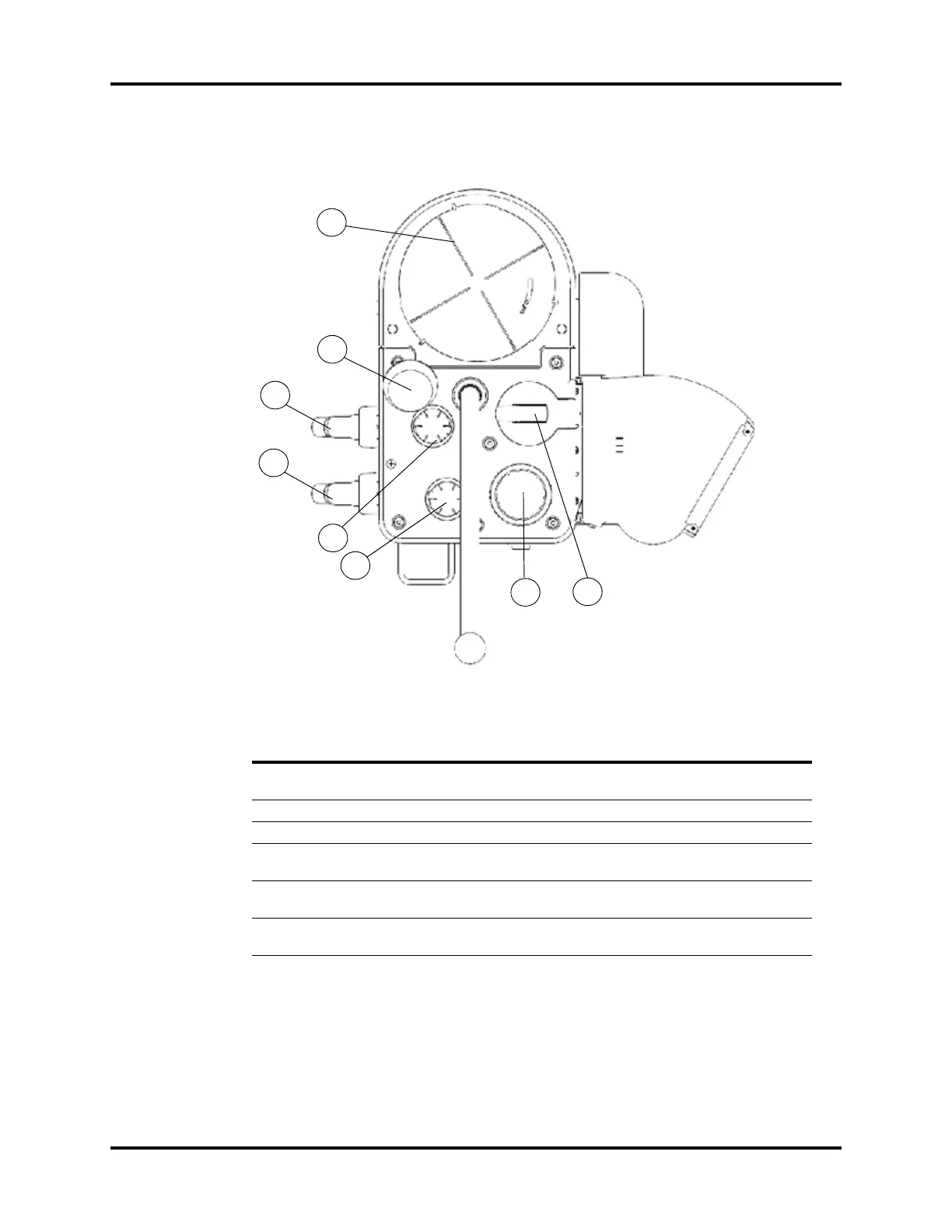
1.2.6 Breathing System (Top View)
FIGURE 1-7 Breathing System (Top View)
PART(S) DESCRIPTION
F1 Bellows (including bellows
dome)
1
Bellows that separates the breathing system gases from the
oxygen drive gas
F2 PAW Gauge
2
Indicates the patient airway pressure
F3 Expiratory Limb Exhaled breathing circuit connection
F4 Inspiratory Limb/ACGO
common outlet
Inhaled breathing circuit connection
F5 Expiration Check Valve Allows flow of expiratory gas from the patient to the re-
breathing system, and prevents reverse flow.
F6 Inspiration Check Valve Allows flow of inspiratory gas to the patient, and prevents
reverse flow.
1
The bellows dome is a transparent cover with graduation marks from 300 to 1500 ml. These marks are for ref-
erence only. Tidal volume (Vt) should be read exclusively from the display of the user interface. Delivered Vt is
a combination of bellows displacement and fresh gas flow.
2
The APL valve and PAW gauge numerics are for reference only. Calibrated patient airway pressure is dis-
played on the user interface.
F1
F3
F2
F5
F6
F8
F7
F4