A7™ Operating Instructions 046-004667-00 1 - 19
Product Description Physical Views
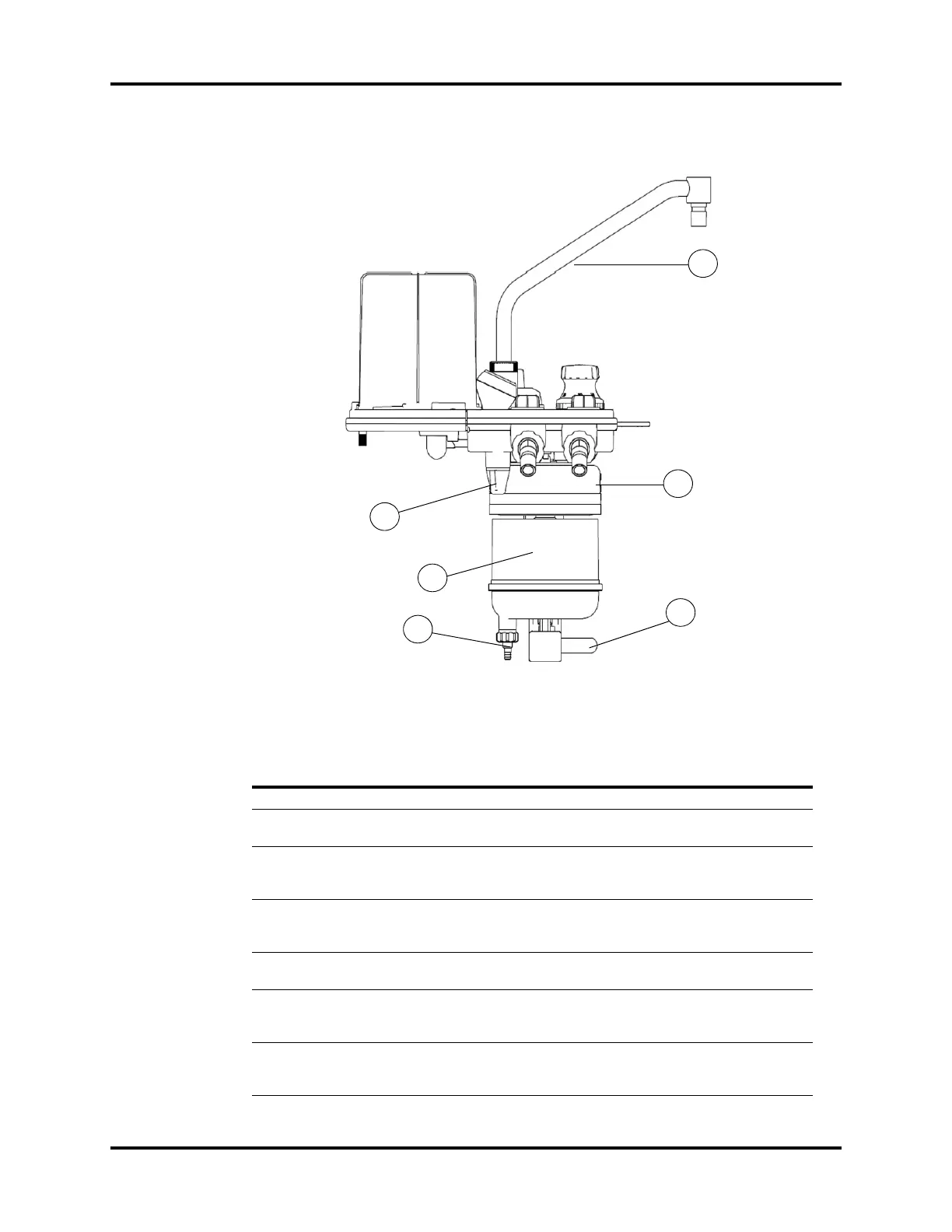
FIGURE 1-9 Breathing System (Left View, the Fixed Height Bag Arm (standard))
PART(S) DESCRIPTION
G1 CO
2
Absorber Canister Container for CO
2
absorbent material loose fill or Pre-Paks)
G2 Condensate Drain Valve Turn counter-clockwise (looking from bottom) to drain water
collected in the absorber canister.
G3 Absorber Canister Lock Lever-type locking mechanism to lock (horizontal position) or
unlock (vertical position) the absorber canister from the
canister assembly.
G4 Water Trap Accumulates condensate from the breathing system. Must be
removed and emptied periodically. To remove, turn clockwise
(looking from top).
G5 Absorber Bypass Assembly Maintains pressure in the breathing circuit when changing
the soda lime contents in the CO
2
absorber canister.
G6 Flexible Bag Arm Provides the interface with the manual ventilation bag. The
flexible bag arm can be adjusted to desired height and the
bag port can be rotated 360°.
G7 Fixed Height Bag Arm Provides the interface for the manual ventilation bag. The
height of fixed bag arm cannot be adjusted and the bag port
is in a fixed direction.
G1
G2
G3
G4
G5
G7